


UG-1262
Hardware Reference Manual
Rev. B | Page 42 of 312
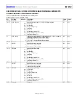
SYSTEM EXCEPTIONS AND PERIPHERAL INTERRUPTS
CORTEX-M3 AND FAULT MANAGEMENT
The
integrates an Arm Cortex-M3 processor, which supports several system exceptions and interrupts generated by
peripherals. Table 40 lists the Arm Cortex-M3 processor system exceptions.
Table 40. System Exceptions
Exception
Number
Type Priority
Description
1
Reset
−3 (highest)
Any reset.
2 NMI
−2
Nonmaskable interrupt connected to a combination of logical ORs of
DVDD_REG pin undervoltage or AVDD_DD pin undervoltage. See Table 23.
3
Hard fault
−1
All fault conditions if the corresponding fault handler is not enabled.
4
Memory
management fault
Programmable
Access to invalid locations.
5 Bus
fault
Programmable
Prefetch fault, memory access fault, data abort, and other address or memory
related faults.
6 Usage
fault
Programmable
Same as undefined instruction executed or invalid state transition attempt.
7 to 10
Reserved
Not applicable
Reserved.
11 SVCALL Programmable
System service call with supervisor mode call (SVC) instruction. Used for system
function calls.
12
Debug monitor
Programmable
Debug monitor for breakpoint, watchpoint, or external debug requests.
13 Reserved
Not
applicable
Reserved.
14 PENDSV Programmable
Pendable request for system service. Used for queuing system calls until other
tasks and interrupts are serviced.
15
SYSTICK
Programmable
System tick timer.
The NVIC controls the peripheral interrupts, which are listed in Table 41. All interrupt sources can wake up the Arm Cortex-M3 core
from flexi mode. Only a limited number of interrupts can wake up the processor from hibernate mode, as shown in Table 41. When the
device is woken up from flexi or hibernate mode, it returns to active mode. If the processor enters flexi or hibernate mode while the
processor is in an interrupt handler, only an interrupt source with a higher priority than the current interrupt can wake up the device.
Higher priority means having a higher value in a bit setting in the Cortex IPRx registers.
Two steps are usually required to configure an interrupt as follows:
1.
Configure a peripheral to generate an interrupt request to the NVIC.
2.
Configure the NVIC for that peripheral request.
Table 41. Interrupt Vectors
Exception Number
IRQx
Vector
Wake Up From
Flexi Hibernate
16
IRQ0
Digital Die Real-Time Clock 1, wake-up timer, hibernate RTC
Yes
Yes
17
IRQ1
Reserved
Not applicable
Not applicable
18
IRQ2
External Interrupt 1 (SYS_WAKE)
Yes
Yes
19
IRQ3
Reserved
Not applicable
Not applicable
20 IRQ4
External Interrupt 3, UART receive wake-up interrupt, and INTCxxx
register interrupt
Yes Yes
21 IRQ5
Reserved
Yes
No
22
IRQ6
Digital Die DVDD_REG pin overrange
Yes
No
23
IRQ7
DVDD pin voltage range
Yes
Yes
24
IRQ8
Reserved
Not applicable
Not applicable
25 IRQ9
GPIO
Interrupt
A
Yes
No
26
IRQ10
GPIO Interrupt B
Yes
No
27
IRQ11
Digital Die General-Purpose Timer 0
Yes
No
28
IRQ12
Digital Die General-Purpose Timer 1
Yes
No
29 IRQ13
Flash
controller
Yes
No
30 IRQ14
UART0
Yes
No
31 IRQ15
SPI0
Yes


