


UG-1262
Rev. B | Page 91 of 312
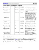
Table 106. Recommended Switch Settings in Low Power Potentiostat Loop
Measurement Name
LPDACCONx
Bit 5 Setting
LPDACSWx
Bits[5:0] Setting
LPTIASWx
Bits[13:0] Setting
Description
Amperometric Mode
0
0xXX (don’t care)
0x302C or 0b11
0000 0010 1100
Normal dc current measurement. External
capacitors to VBIASx and VZEROx DACs are
connected.
Amperometric Mode with
Diode Protection
0 0xXX
(don’t
care)
0x302D or 0b11
0000 0010 1101
Normal dc current measurement with low power
TIA back to back diode protection enabled.
External capacitors to VBIASx and VZEROx DACs
connected.
Amperometric Mode with
Short Switch Enabled
0 0xXX
(don’t
care)
0x302E or 0b11
0000 0010 1110
Normal dc current measurement with short switch
protection enabled. SW1 is closed to connect the
sense electrode input to the output of the low
power TIA. External capacitors to VBIASx and
VZEROx DACs connected. Useful if external
sensor must be charged after a power-up and
many currents flow in or out of the SEx pin.
Amperometric Mode for
Zero-Biased Sensor
0 0xXX
(don’t
care)
0x306C or 0b11
0000 0110 1100
Amperometric mode with SW6 configured to set
sensors reference electrode and sense electrode
to VBIASx level. Potentiostat amplifier inverting
and low power TIA noninverting inputs shorted.
Gives optimal noise performance for zero bias
voltage sensors.
Amperometric Mode for 2-
Lead Sensor
0 0xXX
(don’t
care)
0x342C or 0b11
0100 0010 1100
Amperometric mode with SW10 closed to short
counter electrode to reference electrode
internally.
Chronoamperometry (Low
Power Pulse Test) Using
Low Power TIA
1 0x32 0x0014 or 0b00
0000 0001 0100
VBIASx output generates pulse to counter
electrode. Capacitors on low power DACs are
disconnected. Low power TIA measures sense
electrode current response.
Chronoamperometry (Full
Power Pulse Test) Using
High Speed TIA on Sense
Electrode
1 0x31 0x0094 or 0b00
0000 1001 0100
VBIASx output generates pulse to counter
electrode. Capacitors on low power DACs are
disconnected. High speed TIA measures sense
electrode current response.
Voltammetry (Full Power
Pulse Test) Using High
Speed TIA
1 0x31 0x0094 or 0b00
0000 1001 0100
VBIASx output generates pulse to counter
electrode. Capacitors on low power DACs are
disconnected. High speed TIA measures sense
electrode or the DEx pin current response. High
speed TIA resistors and switches are configured
separately.
Potentiostat Amplifier and
Low Power TIA in Unity-
Gain Mode (Test Mode)
0
0xXX (don’t care)
0x04A4 or 0b00
0100 1010 0100
Potentiostat amplifier in unity gain mode,
output to CEx pin. Low power TIA in unity gain
mode, output to RCx_1 pin. Useful for checking
VBIASx or VZEROx DAC outputs.
Electrochemical Impedance Spectroscopy
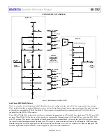
In many electrochemical applications, there is significant value to carrying out a diagnostic measurement. A typical diagnostic technique
is carrying out an impedance measurement on the sensor. For some sensor types, the dc bias on the sensor must be maintained when
carrying out the impedance measurement. The
facilitates this measurement. To maintain the dc bias on the sensor, set
LPDACCONx, Bit 5 = 1. VZEROx is set to the input of the high speed TIA, and the high speed DAC is used to generate an ac signal. The
level of the ac signal is set via the VBIASx output of the low power DAC. The voltage on the SE0 and SE1 pins is maintained by VZEROx.
The high speed DAC dc buffers must also be enabled by setting AFECON, Bit 21.


