Firmware Pages and Descriptions
143
VG-Series Modero Touch Panels
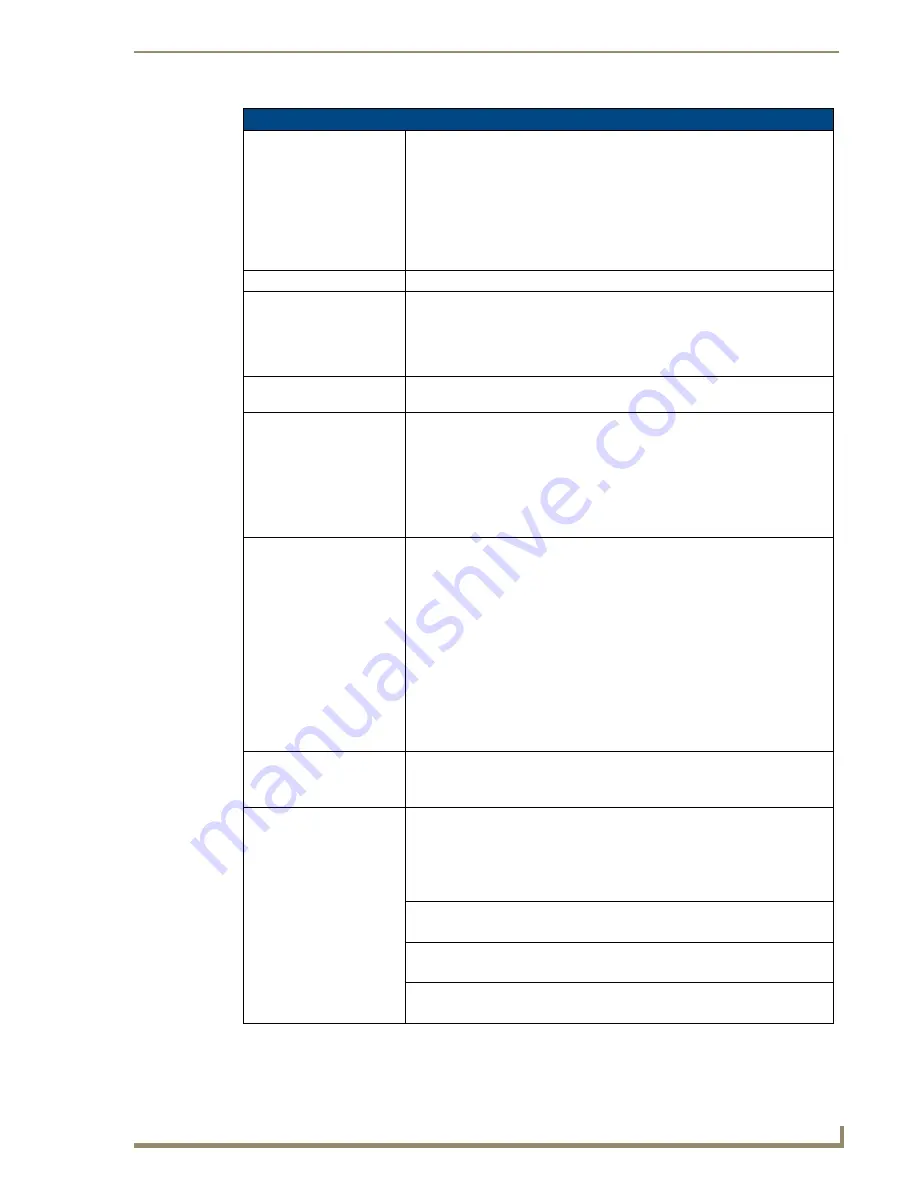
RGB Adjustment Page Elements (Cont.)
Settings:
• The
Default Settings
button sets the RGB settings to their default values
(indicated in this table).
• The
Undo Changes
button disregards any changes made on the page since
the last settings were saved.
• The
Save Settings
button saves any changes made to the RGB Adjustment
page.
• The
Sync on Green
button sets the NXA-RGB card to search for the sync
signal on Green signal.
Version:
Displays the firmware version being used by the internal NXA-RGB card.
BOB Version:
Displays the firmware version of the communicating NXA-AVB/RGB Breakout
Box.
• If firmware is updated to either the panel or the breakout box, both units must
be power-cycled for the panel to detect and display the BOB firmware
version.
Status:
Displays the input signal properties of the signal routed through the internal
NXA-RGB card (H-pixel x V-pixel @ Hz). An example is: 1024x768@85Hz.
Cable Variance:
Allows you cycle through a choice of available cable compensation parameters
(
Short
,
Medium,
and
Long
).
• This field adjusts the cable compensation for any signal degradation over a
selected cable length.
• This adjustment is done by using preset calculations to take into account the
length and type of cable being used to transmit the signal.
• Toggling the field can correct some signal problems.
RGB Input Resolution:
Use the UP/DN buttons to alter the input resolution of the RGB signal being
routed through the internal NXA-RGB card.
• Supported Input resolutions are:
-
Auto
: automatically detects the incoming signal.
This is the
recommended setting and should be used as the default selection.
- 560 x 192, 560 x 384, 640 x 350, 640 x 416, 640 x 480, 720 x 532,
800 x 600, 900 x 720, 1024 x 768, 1280 x 768, 1280 x 800, 1152 x 864,
1280 x 1024, 1600 x 1200, HD 480p, HD, 720p, and HD 1080i.
•
Note
: These displayed resolutions correspond to the supported input
resolution of the NXA-RGB card.
• Note: When using 1024 x 768, 1280 x 768, or 1280 x 800 it is
recommended that you select those specific resolutions using the input
adjustment UP/DN buttons.
Phase:
Use either the slider or the UP/DN buttons to alter the RGB tracking/signal
level.
• Range = 0 - 31, default = 0.
Geometry:
Provides an on-screen RGB Geometry popup dialog that allows you to select
from several location and size adjustment settings.
• Press the
Adjust
button to open the RGB Geometry popup dialog.
• Use the
Hide
button to close the popup.
• Range = 0 - 255, default = 0.
H Position
Use the UP/DN buttons to alter the horizontal position level.
• Range = 0 - 255, default = 0.
H Size
Use the UP/DN buttons to alter the horizontal size level.
• Range = 0 - 255, default = 0.
V Position
Use the UP/DN buttons to alter the vertical position level.
• Range = 0 - 255, default = 0.
Summary of Contents for Modero NXT-1500VG
Page 4: ......
Page 62: ...Touch Panel Accessories 52 VG Series Modero Touch Panels...
Page 100: ...Installation Procedures 17 Panels 90 VG Series Modero Touch Panels...
Page 178: ...Firmware Pages and Descriptions 168 VG Series Modero Touch Panels...
Page 250: ...Appendix 240 VG Series Modero Touch Panels...
Page 251: ...Appendix 241 7 Modero Widescreen Touch Panels...


