background image

Upgrading Modero Firmware

128

VG-Series Modero Touch Panels

11.

Click 

Close

 (

after the panel reboots

) to return to the main program.

12.

Right-click the associated System number and select 

Refresh System

. This causes a refresh of all 

project systems, establishes a new connection to the Master, and populates the System list with 
devices on your particular system.

Upgrading Accessory Devices via an IP Address

The following accessory devices are firmware upgradeable:


NXA-BASE/B Battery Base (

FG2255-10

)


NXA-RGB card (

FG2260

)


NXA-AVB/RGB Breakout Box (

FG2254-11

)

These devices are not given a unique device numbers which would ordinarily appear within the Online 
Tree tab of NetLinx Studio. They appear below the target which they are either communicating with 
(NXA-AVB/RGB) or a part of (NXA-BASE/B or NXA-RGB card) as seen below in FIG. 99.    

The only way to upgrade the firmware of an accessory item is to send the accessory’s firmware through a 
target panel. Its this panel’s device number which is entered within the 

Send to NetLinx Device transfer


dialog in Studio.

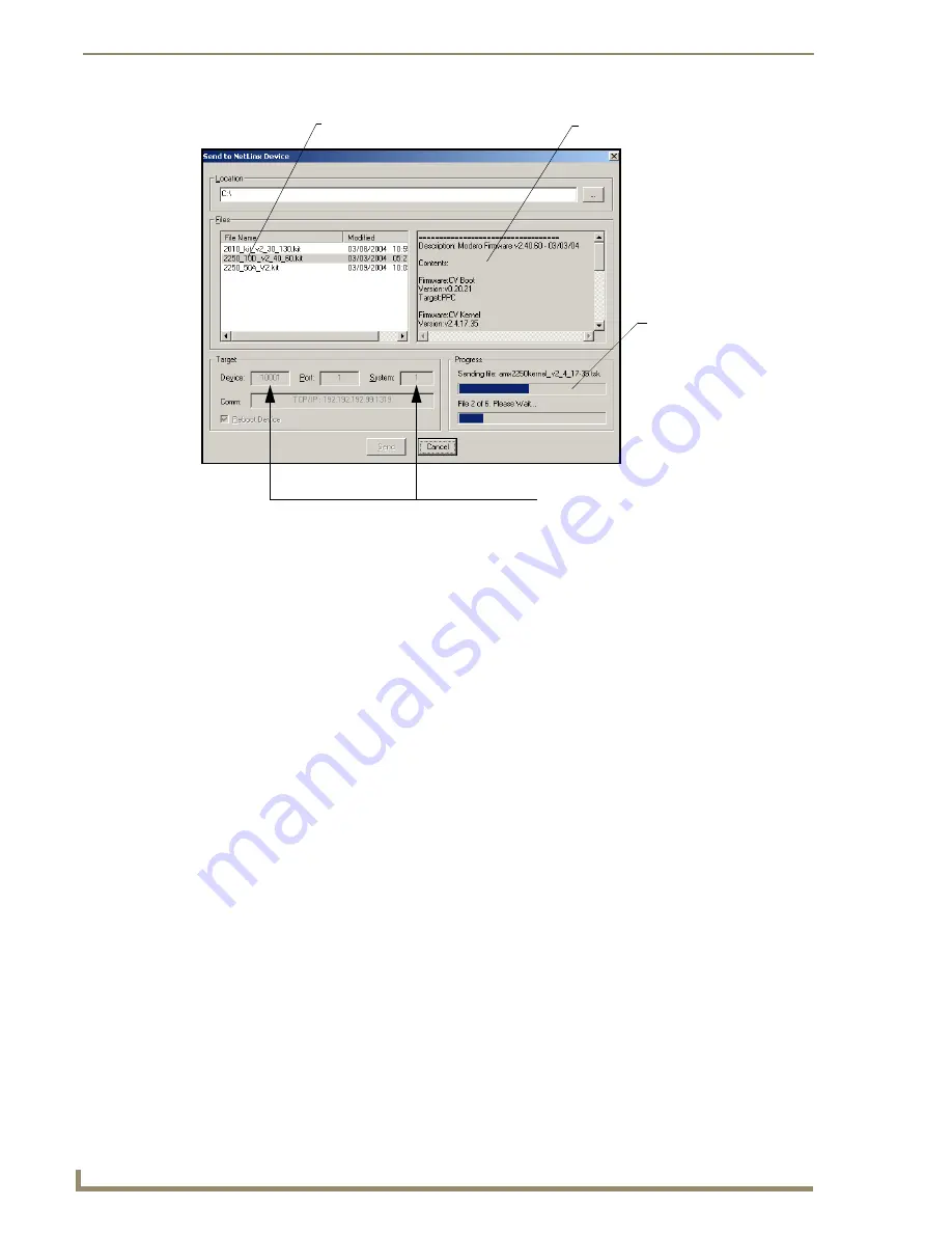
FIG. 98  

Send to NetLinx Device dialog (showing Modero firmware update via IP)

Selected Firmware file

Description field for selected KIT file 

Device 

value

 and System 

number

must match the values 
listed in the Workspace window

Firmware download
status

Summary of Contents for Modero NXT-1500VG

Page 1: ...Operation Reference Guide Touch Panels Modero VG Series G4 Touch Panels NXD NXT 1200VG NXD NXT 1500VG and NXD NXT 1700VG Last Revised 10 1 2008...

Page 2: ...whichever is greater Products that are returned and exhibit signs of damage or unauthorized use will be processed under the Non Warranty Repair Policy AMX will continue to provide Warranty Repair Serv...

Page 3: ...wever there is no guarantee that interference will not occur in a particular installation If this equipment does cause harmful interference to radio or television reception which can be determined by...

Page 4: ......

Page 5: ...Wiring the NXA AVB RGB for Balanced Audio 25 Preparing your panel for Pass Thru Control using the NXA AVB RGB Breakout Box 26 Wiring for Pass Thru Computer Control 27 NXA MTC RGB Combo Table Top Cable...

Page 6: ...ons 49 Powering the NXT CHG 50 Reading NXT CHG LED Indicator 50 Charging the NXT BP batteries using the NXT CHG 50 Recalibrating the batteries 51 Installation Procedures 12 and 15 Panels 53 Overview 5...

Page 7: ...Mount Kit NXA RK17 86 Wiring Guidelines for the 1700VG Panels 87 Preparing captive wires 87 Wiring a power connection 87 Audio Video Port Connections and Wiring 88 Ethernet RJ 45 Port Connections and...

Page 8: ...n section NetLinx Master Ethernet IP Address Listen Mode 114 Master Connection section NetLinx Master Ethernet IP Address Auto Mode 115 Using G4 Web Control to Interact with a G4 Panel 116 Using your...

Page 9: ...Page 161 Wireless Settings Page 162 System Settings Page 166 Displaying Stream Content 169 Overview 169 Requirements for Receiving Streamed Content 170 Setting up a Modero Panel to Receive and Displa...

Page 10: ...ubleshooting 231 Appendix 235 Text Formatting Codes for Bargraphs Joysticks 235 Text Area Input Masking 236 Input mask character types 236 Input mask ranges 237 Input mask next field characters 237 In...

Page 11: ...se Moderos feature full support for standard MPEG 2 streaming video as well as MP3 and AAC streaming audio The NXA AVB RGB Breakout Box FG2254 11 facilitates the installation and distribution of video...

Page 12: ...D 1200VG and NXT 1200VG The following table outlines the specifications for VG Series of 12 Modero panels Modero Multimedia Touch Panels VG Series with RGB Kits NXD 1200VG FG2251 61RGB 12 Modero Multi...

Page 13: ...partment Pass thru Computer Control via the NXA RGB card RGB or Component input Streaming MPEG 2 and MPEG 4 digital video support Streaming MP2 MP3 and AAC digital audio support Support of the latest...

Page 14: ...Kit configuration or within the NXA RGBKIT upgrade kit for previous Video Kit fitted VG Series panels Routes RGB and computer control pass thru signals to from a Modero panel up to 200 ft 60 9 m RJ 45...

Page 15: ...Step 5 Confirm and View the current AMX USB device connections section on page 100 for more information Operating Storage Environment Operating Temperature 10 C 50 F to 40 C 104 F Operating Humidity...

Page 16: ...NXT models only NXA KLB Kensington Lock Kit for NXT panels FG2259 10 optional only with NXT models NXA MTC RGB Modero 10 foot Table Top Cable with RGB connector CA2250 70 This cable is not wall rated...

Page 17: ...0VG Fully lowered 7 45 x 14 95 x 11 72 18 92 cm x 37 97 cm x 29 77 cm CB TP15 conduit wallbox 13 48 x 14 18 x 3 49 34 24 cm x 36 00 cm x 8 85 cm MB TP15 VESA mounting box 14 37 x 15 19 x 3 59 36 50 cm...

Page 18: ...er Control G4Web Control Dynamo TakeNote and PictureFrame USB mouse keyboard programming ports Wired Ethernet 10 100 and Wireless Ethernet 802 11g Supported Audio Sample Rates 48000Hz 44100Hz 32000Hz...

Page 19: ...ed VG Series panels Routes RGB and computer control pass thru signals to from a Modero panel up to 200 ft 60 9 m RJ 45 connector provides RGB Component video signals being routed from the rear RGB Com...

Page 20: ...evice connections section on page 100 for more information Operating Storage Environment Operating Temperature 10 C 50 F to 40 C 104 F Operating Humidity 20 to 85 RH Storage Temperature 20 C 4 F to 60...

Page 21: ...ensington Lock Kit for NXT panels FG2259 10 optional only with NXT models NXA MTC RGB Modero 10 foot Table Top Cable with RGB connector CA2250 70 This cable is not wall rated for NXD models Several it...

Page 22: ...3 29 x 17 84 x 12 44 35 31 cm x 45 31 cm x 31 60 cm NXT 1700VG Fully lowered 6 23 x 17 84 x 12 44 15 82 cm x 45 31 cm x 31 60 cm CB TP17 conduit wallbox 13 55 x 17 07 x 3 49 34 43 cm x 43 38 cm x 8 85...

Page 23: ...er Control G4Web Control Dynamo TakeNote and PictureFrame USB mouse keyboard programming ports Wired Ethernet 10 100 and Wireless Ethernet 802 11g Supported Audio Sample Rates 48000Hz 44100Hz 32000Hz...

Page 24: ...ted VG Series panels Routes RGB and computer control pass thru signals to from a Modero panel up to 200 ft 60 9 m RJ 45 connector provides RGB Component video signals being routed from the rear RGB Co...

Page 25: ...ce connections section on page 100 for more information Operating Storage Environment Operating Temperature 10 C 50 F to 40 C 104 F Operating Humidity 20 to 85 RH Storage Temperature 20 C 4 F to 60 C...

Page 26: ...panels FG2259 10 optional only with NXT models NXA MTC RGB Modero 10 foot Table Top Cable with RGB connector CA2250 70 This cable is not wall rated for NXD models NXA PCI80211G Wireless Card FG2255 04...

Page 27: ...eyboards and keypads will reflect any external keystrokes sent from the external USB keyboard 1700VG Panel Specifications Cont Other AMX Equipment Cont Upgrade Compact Flash factory programmed with fi...

Page 28: ...ntroduction 18 VG Series Modero Touch Panels Cleaning the Touch Overlay You should clean the touch screen overlay after each day s use Always use clean cotton cloths and a spray bottle containing wate...

Page 29: ...ands out amongst all previous AMX Breakout Boxes in that it is firmware upgradeable feeds high quality video signals via RJ 45 cables and provides keyboard and mouse pass through functionality via the...

Page 30: ...ouch panel RJ 45 connector provides differential audio video signals between the touch panel and the box This connector routes Composite video Stereo left right audio and microphone audio RJ 45 connec...

Page 31: ...wist 7987 cable versus standard CAT5 or other Ethernet compliant cables The pinout of this RGB connector is given in the table below NXA AVB RGB Specifications Cont Other AMX Equipment AC RK Equipment...

Page 32: ...Red Red signals Cr 2 Green Green signals Y 3 Blue Blue signals Cb 4 N A Not used 5 GND Signal Ground 6 RAGND Red analog ground 7 GAGND Green analog ground 8 BAGND Blue analog ground 9 N A Not used 10...

Page 33: ...gnal feed to the panel s internal NXA RGB input card FIG 4 provides a layout of the wiring connection both into and from the breakout box The rear panel wiring connections are described below from lef...

Page 34: ...nel is divided into GND IN and IN terminal cable connectors 2 sets of 3 for each channel An example of this cable is to strip the ends of 2 RCA audio cables and insert them into their respective locat...

Page 35: ...and so gets cancelled by the receiving equipment The 3 wires used in a typical XLR lead are often referred to as Ground Live Hot and Return Cold Live and Return carry the in phase and out of phase ver...

Page 36: ...h the necessary Video Fill Component RGB video properties selected Video Fill allows you to select from a drop down list of video formats that are supported by the touch panel specified in your projec...

Page 37: ...and from the panel via this two way connector 5 Verify the panel has been configured to communicate by connecting an RJ 45 10 100baseT Ethernet connector from the rear Ethernet port on the breakout b...

Page 38: ...routes VGA and Component video signals between the panel and the AVB RGB Breakout Box 2 pin 3 5 mm mini Phoenix power connector to route power from the external breakout box to the target panel Includ...

Page 39: ...Suppression Ferrites 04 0014 Installation Kit for 10 NXT panels KA2259 01 2 pin 3 5 mm mini Phoenix connector 41 5025 One CAT5 Table Top Suppression Ferrite 04 0014 One cylindrical CAT5 USB Mouse Supp...

Page 40: ...re detailed information 3 Insert the panel end of the Black RJ 45 Audio Video cable into the groove along the inside of the enclosure 4 Snap the enclosure shut with the cable inside and you re done Wi...

Page 41: ...ndow on the Modero panel The NXA RGB card must be used with the NXA AVB RGB Breakout Box This breakout box allows the Modero to accept and display high bandwidth and high quality RGB as well as HDTV C...

Page 42: ...nnector RJ 45 connector provides RGB Component video signals being routed from the rear RGB Component input ports and touch control information to the RJ 45 RGB connector on the NXA RGB card installed...

Page 43: ...t cables The pinout of this RGB connector is given in the table below NXA RGB Supported Resolutions and Formats Resolutions Refresh Rates Descriptions VGA Compatible signals 560 x 192 60 Hz Apple II 5...

Page 44: ...cess the internal circuit board removing the existing part and replacing them with the upgrade components as described in the following sections RGB RJ 45 Connector Pinouts and Signals Pin Color Funct...

Page 45: ...ss Card FIG 14 FCC Statement NXA PCI80211G Specifications Dimensions HWD 0 02 x 2 13 x 4 66 5 0 mm x 54 0 mm x 118 4 mm Description Direct Sequence Spread Spectrum DSSS CCK 802 11g Wireless mini PCI c...

Page 46: ...ion Orthogonal Frequency Division Multiplexing OFDM Complementary Code Keying CCK Network Architecture Ad hoc mode Peer to Peer Infrastructure mode Network Standard IEEE Compliant 802 11b and 802 11g...

Page 47: ...remove the eight Housing Screws 4 Rotate the panel back over while gripping the entire unit with outer housing and rest the base back on a flat surface 5 Gently tilt the LCD backward to a 45 angle NXA...

Page 48: ...ct 2 Locate the mini PCI card connector on the main board FIG 16 and FIG 17 3 Carefully remove the gold tipped terminal ends of the antenna from their factory default connectors on the main board The...

Page 49: ...fully but firmly insert the NXA RGB card into the RGB connector slot on the main board until both the card rests atop the four raised securing holes and the RGB RJ 45 connector is evenly aligned with...

Page 50: ...removal grooves located on either side of the card and gently pry the card out of the slot FIG 21 Repeat this process on the opposite card removal groove This alternating action causes the card to wig...

Page 51: ...aligned over the installation holes and the tilt bracket prevents any further forward movement FIG 19 4 Gently press down on the housing toward the base until it is securely positioned over the circu...

Page 52: ...mall amount of pressure to remove it from the main unit 2 Place the LCD facedown onto a soft cloth to expose the under side of the unit This step helps prevent scratching of the LCD 3 Unscrew the Ster...

Page 53: ...he raised securing holes on the main board Refer to the Step 3 Install the NXA RGB Card Component NXT section on page 39 for more information Step 4 Install the new Compact Flash Memory card NXD 1 Com...

Page 54: ...ttery Base This battery incorporates an on board battery life indicator The NXT BP battery can be charged through either the base when connected to the Modero panel or through an optional NXT CHG Mode...

Page 55: ...dero Panel section on page 46 for more detailed installation and usage instructions Product Specifications FIG 26 NXA BASE B and NXT BP combo NXA BASE B Specifications Dimensions HWD 1 13 x 8 63 x 11...

Page 56: ...o the NXT panel without any NXT BP batteries 1 Power Off the panel before attempting to use the NXA BASE B 2 Place the empty battery base onto a flat level surface 3 Verify the alignment of the Panel...

Page 57: ...ctly connect to a power supply but rather receives its power directly from the Modero panel through the Panel Interface connector 1 With the panel mounted on the battery base open the battery compartm...

Page 58: ...ting the panel is receiving power Charging the NXT BP batteries with the NXA BASE B 1 Follow the procedures from the previous sub section to attach the NXT touch panel to the NXA BASE B 2 Insert each...

Page 59: ...d two NXT BP batteries NXT BP and NXT CHG Specifications Dimensions HWD 1 13 x 8 63 x 11 81 2 86 cm x 21 91 cm x 30 00 cm Power Requirements NXT BP Battery Voltage 11 1 Volts NXT CHG 90 264 VAC 47 63...

Page 60: ...king the NXT BP battery charge section on page 46 to confirm the percentage of charge remaining on the batteries 2 Provide power to the charger as outlined in the Powering the NXT CHG section on page...

Page 61: ...t from the Modero on screen Battery Base page Refer to the Battery Base Page section on page 151 for more detailed Battery Base page information 1 Place the selected battery securely into Slot 1 left...

Page 62: ...Touch Panel Accessories 52 VG Series Modero Touch Panels...

Page 63: ...Step 3 Install the NXA RGB Card Component NXT section on page 39 Upgrading to the MB TP12 MB TP15 VESA Mounting Kit Upgrading the existing back box with the new VESA Mounting Kit on both the 12 FG031...

Page 64: ...internal panel casing Installing the MP TP12 15 Back Box 1 Unscrew the four pan head Housing screws 8 32 from the MP TP12 15 rear plastic cover 2 Gently place the MP TP12 15 back box over the interna...

Page 65: ...it into the opening on the rear plastic cover FIG 34 Finalizing the installation 1 Gently place the rear plastic cover over the NXD panel with LCD and MB TP12 15 back box 2 Insert the protruding cable...

Page 66: ...to their pre drilled holes along the edges of the NXD unit FIG 34 This step secures the NXD unit to the rim of the rear plastic cover 9 Align a VESA mount connector purchased separately to the four 8...

Page 67: ...r s installation procedures for further surface mounting procedures FIG 36 MB TP15 Mounting contact surface area 3 23 82MM 72 18MM 4 52 115MM 3 83 97MM When installing a VESA mount to the rear plastic...

Page 68: ...of the conduit box FIG 38 by using either nails or screws 2 Remove any necessary wiring knockouts from the optional conduit box CB TP12 15 C in FIG 39 where the necessary cables are threaded through f...

Page 69: ...B in FIG 39 by gripping the faceplate and pulling with gentle outward force 2 Verify the incoming RJ 45 Ethernet USB and any other audio video cables have been properly threaded through the wiring kn...

Page 70: ...r connector on the 12 VDC compliant power supply and apply power Installing the NXD into drywall using Expansion Clips Expansion clips are mounted through the four oval holes located at the top and bo...

Page 71: ...el 5 Connect all data and power wiring connectors to their corresponding locations along the side of the un powered NXD touch panel Verify the terminal end of the power cable is not connected to a pow...

Page 72: ...the cutout until the Mounting Tabs on the NXD unit lie flush against the wall FIG 41 10 Tighten the drywall clip sets screws and clips until the Mounting Tabs are securely fastened and flush against...

Page 73: ...that the outer frame Mounting Tabs must be installed flush against the mounting surface It is recommended that you cutout the surface slightly smaller than what is outlined in the installation drawin...

Page 74: ...other audio video wiring from their terminal locations through the cutout opening Refer to the Wiring Guidelines for the 1200VG and 1500VG Panels section on page 68 for pinout descriptions Leave enou...

Page 75: ...terminal end of the power cable from the power supply 8 Carefully slide the main unit into the cutout until the Mounting Tabs of the NXD unit lie flush against the wall 9 Insert and secure the four 4...

Page 76: ...ck to accommodate any re positioning of the panel 3 Connect all data and power wiring connectors to their corresponding locations along the side of the un powered NXD touch panel Verify the terminal e...

Page 77: ...ews in a clockwise direction 8 Insert the NXA RK with connected NXD unit into the equipment rack making sure to align the screw holes along the sides on the NXA RK with the holes in the equipment rack...

Page 78: ...eed a wire stripper and flat blade screwdriver to prepare and connect the captive wires 1 Strip 0 25 inch 6 35 mm of insulation off all wires 2 Insert each wire into the appropriate opening on the con...

Page 79: ...nd Wiring FIG 49 describes the blink activity for the Ethernet 10 100 Base T RJ 45 connector and cable The Ethernet cable is connected to the rear of Table Top and side of the Wall Mount panels Audio...

Page 80: ...45 pinouts and signals for the Ethernet RJ 45 connector and cable Ethernet RJ 45 Pinouts and Signals Pin Signals Connections Pairing Color 1 TX 1 1 1 2 Orange White 2 TX 2 2 Orange 3 RX 3 3 3 6 Green...

Page 81: ...RGB Card Component NXT section on page 39 Upgrading the Back Box with the MB TP17 VESA Housing Upgrading the existing back box with the new VESA Mounting Kit FG033 50 requires 3 main processes Removi...

Page 82: ...the right side of the panel 3 Re install and secure the four pan head Housing Screws into their pre drilled holes along the edges of the MB TP17 back box FIG 52 and secure them using a grounded Phill...

Page 83: ...opening on the rear plastic cover FIG 52 Finalizing the installation 1 Gently place the rear plastic cover over the NXD panel with LCD and MB TP17 back box 2 Insert the protruding cables coming out fr...

Page 84: ...nt connector purchased separately to the four 8 32 screw holes on the back of the rear plastic cover FIG 53 10 Insert the four provided 8 32 screws through the VESA mount s four holes and then into th...

Page 85: ...bs must be mounted flush against the outside of the sheetrock This step determines whether or not the mounting stud is notched cutout out to fit the conduit box 1 Measure the distance between the insi...

Page 86: ...7 to the block through the stud fastening holes located on the inside of the Conduit Box FIG 56 by using either nails or screws 10 Remove any necessary wiring knockouts from the optional conduit box C...

Page 87: ...faceplate and pulling with gentle outward force 2 Verify the incoming RJ 45 Ethernet and any other audio video cables have been properly threaded through the wiring knockouts on the left of the condui...

Page 88: ...B in FIG 57 Make sure to align the Microphone Light and PIR Motion sensor locations to their respective openings on the front bezel faceplate 9 Reconnect the terminal RJ 45 Ethernet and any optional...

Page 89: ...ons vary based on location and building codes FIG 58 shows show to mount and position the main NXD unit into a pre wall environment for use with drywall clips There is no notching of a beam in this me...

Page 90: ...e magnetic faceplate bezel A in FIG 60 from the main NXD unit B in FIG 60 by gripping the faceplate and pulling with gentle outward force 6 Follow the procedures outlined within Steps 1 5 on page 42 t...

Page 91: ...This value reflects the cutout depth necessary for the mounting ridge on the back box to be flush against the surface 10 Thread the incoming RJ 45 Ethernet and any other audio video wiring from their...

Page 92: ...grooves face upwards and the bottom clip grooves face downwards so they extend away from the Main unit 16 Carefully insert the main unit with expansion clips into the cutout until the Mounting Tabs o...

Page 93: ...er the drywall has been installed A horizontal beam can be installed framed below the back box to provide lower support With an existing wall in place continue with steps 3 and 4 to notch one or both...

Page 94: ...outward force FIG 61 NXD 1700VG Wall Mount panel dimensions using 4 mounting screws FIG 62 Wall Mount panel NXD installation using screws B Main NXD unit consists of the touch panel and housing A Face...

Page 95: ...rresponding locations along the side of the un powered NXD touch panel Verify the terminal end of the power cable is not connected to a power supply before plugging in the 2 pin power connector The US...

Page 96: ...ding locations along the side of the un powered NXD touch panel Verify the terminal end of the power cable is not connected to a power supply before plugging in the 2 pin power connector 4 Test the in...

Page 97: ...flat blade screwdriver to prepare and connect the captive wires 1 Strip 0 25 inch 6 35 mm of insulation off all wires 2 Insert each wire into the appropriate opening on the connector according to the...

Page 98: ...ibes the blink activity for the Ethernet 10 100 Base T RJ 45 connector and cable The Ethernet cable is connected to the rear of Table Top and side of the Wall Mount panels Audio Video RJ 45 Pinout Inf...

Page 99: ...inouts and signals for the Ethernet RJ 45 connector and cable Ethernet RJ 45 Pinouts and Signals Pin Signals Connections Pairing Color 1 TX 1 1 1 2 Orange White 2 TX 2 2 Orange 3 RX 3 3 3 6 Green Whit...

Page 100: ...Installation Procedures 17 Panels 90 VG Series Modero Touch Panels...

Page 101: ...ouch panel pages When the panel is ready the AMX Splash Screen is replaced by the Initial Panel Page FIG 67 Calibrating the Modero Panel 1 Press and hold the grey Front Setup Access button FIG 68 for...

Page 102: ...ssing the Back button to return to the Protected Setup page FIG 69 Touch Panel Calibration Screens The request to touch the crosshairs is the first on screen message Calibration successful is the seco...

Page 103: ...e is 10001 and the range is from 1 32000 USB input devices must be plugged into the rear or side USB connectors before the G4 panel is powered up The panel will not detect a USB connection of this typ...

Page 104: ...ected Setup button located on the lower left of the panel page to open the Protected Setup page 11 Press the System Settings button located on the Protected Setup page to open the System Settings page...

Page 105: ...hin the Choose Components dialog select the features you wish to install The Driver option is selected by default and is the only item required 6 Click the Install button to continue with the installa...

Page 106: ...le to the power connector on the rear side of the touch panel and then apply power 3 After the panel powers up press and hold the grey Front Setup Access button for 3 seconds to continue with the setu...

Page 107: ...hen told that a digital signature was not found This action accepts the installation of the new USB driver The panel is now configured to communicate directly with the PC This process completes the as...

Page 108: ...ice is connected to the computer it will appear as a new hardware device and will need to be associated again with the driver refer to Step 2 Confirming the Installation of the USB Driver on the PC se...

Page 109: ...Virtual System The default System value is one 11 Right click on the Empty Device Tree System entry and select Refresh System to re populate the list The panel will not appear as a device below the vi...

Page 110: ...communication and the Virtual Master setup within NetLinx Studio its now time to verify the panel is ready to receive files 3 Click the OnLine Tree tab in the Workspace window to view the devices on...

Page 111: ...he panel will first check to see if there is an installed wireless interface card and then communicate to the WAP using the Wireless Settings assigned within the Wireless Settings page The WAP communi...

Page 112: ...ireless communication using a DHCP Address 1 Press the Protected Setup button located on the lower left of the panel page to open the Protected Setup page and display an on screen keypad 2 Enter 1988...

Page 113: ...entering the IP information 7 Repeat the same process for the Subnet Mask and Gateway fields 8 Press the optional Host Name field to open the Keyboard and enter the Host Name information 9 Press Done...

Page 114: ...page 6 From within the Wireless Settings section of the Wireless Settings page touch the Network Name SSID field FIG 80 7 From the Service Set Identifier keyboard enter the SSID name used by your tar...

Page 115: ...erator on Modero panels use the same key generation formula all panels will generate identical keys for the same Passphrase The generators used on WAPs will not produce the same key as the Modero gene...

Page 116: ...System default Open System Authentication allows any device to join the network if the panel s SSID matches the WAP s SSID An Open System is recommended for communication between Modero panels and an...

Page 117: ...n WEP Passphrase keyboard FIG 82 enter a character string or word such as AMXPanel and press Done when you have finished As an example enter the word AMXPanel using a 128 bit hex digit encryption Afte...

Page 118: ...ood Very Good and Excellent Refer to the NXA WAP200G Instruction Manual for more detailed setup and configuration procedures Configuring multiple wireless Moderos to communicate to a target WAP200G 1...

Page 119: ...net 1 Select Protected Setup System Settings located on the lower left to open the System Settings page 2 Locate the IP Settings section of this page 3 Toggle the DHCP Static field from the IP Setting...

Page 120: ...ection of this page to begin configuring the communication parameters for the target Master Step 2 Choosing a Master Connection Mode Setting There are three Ethernet MODE settings used in the Master C...

Page 121: ...anel 4 Verify the green Ethernet LED from the rear Ethernet port on the Master is illuminated indicating a proper connection 5 Verify the yellow LED from the rear Ethernet port on the Master is blinki...

Page 122: ...the Master s UI 7 Click the Edit Settings button on the Communications Settings dialog to open the Virtual NetLinx Master Settings dialog FIG 85 8 From within this dialog enter the System number defa...

Page 123: ...lecting URL the System Number field becomes read only grey because the panel pulls this value directly from the communicating target Master virtual or not A Virtual Master system value can be set with...

Page 124: ...panel Master Connection section NetLinx Master Ethernet IP Address Listen Mode In this mode you must add the Modero panel IP Address into the URL List of the Master using NetLinx Studio This mode sets...

Page 125: ...ue Type field until Ethernet is selected from the Master Connection section of the System Settings page 2 Press the Mode field until the choice cycles to the word Auto 3 Press the System Number field...

Page 126: ...r 7 The Network Interface Select field is read only and displays the method of communication to the web Verify you have selected the proper interface connection as this field does not auto detect the...

Page 127: ...word 14 Press the Web Control Port field to open the Web Port Number keypad 15 Within the keypad enter a unique numeric value to be assigned to the port the VNC Web Server is running on The default va...

Page 128: ...password is required for access or configuration Both HTTP and HTTPS Ports are enabled by default via the Manage System Server page If the Master has been previously configured for secured communicati...

Page 129: ...ommunication you are using it can be found in either the Wired Ethernet System Settings IP Settings section within the IP Address field Wireless Wireless Settings IP Settings section within the IP Add...

Page 130: ...ick OK to send the password to the panel and begin the session A confirmation message appears stating Please wait Initial screen loading The secondary window then becomes populated with the same G4 pa...

Page 131: ...ing the mini USB connector to the panel Step 1 Configure the panel for a USB Connection Type 1 After the installation of the USB driver has been completed confirm the proper installation of the large...

Page 132: ...System Settings page Step 2 Prepare NetLinx Studio for communication via the USB port 1 Launch NetLinx Studio 2 x default location is Start Programs AMX Control Disc NetLinx Studio 2 NetLinx Studio 2...

Page 133: ...configured properly using the steps outlined in the previous two sections 2 With the panel already configured for USB communication and the Virtual Master setup within NetLinx Studio its now time to...

Page 134: ...he Device value associated with the panel and the System number associated with the Master listed in the OnLine Tree tab of the Workspace window The Port field is greyed out 10 Click the Reboot Device...

Page 135: ...ss and Gateway information 2 Launch NetLinx Studio 2 x default location is Start Programs AMX Control Disc NetLinx Studio 2 NetLinx Studio 2 3 Select Settings Master Communication Settings from the Ma...

Page 136: ...ttings 17 Click Reboot from the Tools Reboot the Master Controller dialog and wait for the System Master to reboot The STATUS and OUTPUT LEDs should begin to alternately blink during the incorporation...

Page 137: ...ick on the desired Kit file link and after you ve accepted the Licensing Agreement verify you have downloaded the Modero Kit file to a known location 6 From within Studio select Tools Firmware Transfe...

Page 138: ...1 These devices are not given a unique device numbers which would ordinarily appear within the Online Tree tab of NetLinx Studio They appear below the target which they are either communicating with N...

Page 139: ...e grey Front Setup Access button for 3 seconds to open the Setup page 3 Press the Battery Base button to open the Battery Base page FIG 100 FIG 99 Location of Firmware version information within NetLi...

Page 140: ...Files and from within the Modero section of the web page locate the Modero Battery Base section of the website 5 Click on the desired Kit file link and after you ve accepted the Licensing Agreement ve...

Page 141: ...ront Setup Access button below the LCD for 3 seconds to access the Setup page 14 Press the Battery Base button to open the Battery Base page and confirm that the version is no longer 0 00 FIG 101 Send...

Page 142: ...Press the Video Adjustment RGB Adjustment buttons to open the RGB Adjustment page FIG 102 This page displays the firmware for both the internal NXA RGB card and the communicating external NXA AVB RGB...

Page 143: ...button to access the Panel Information page and view panel specific information such as resolution memory etc read only Refer to the Panel Information Page section on page 137 for more detailed infor...

Page 144: ...monitor NXT BP Modero Power Pack parameters This button only appears when a Modero Table Top panel NXT is connected to an NXA BASE B battery base Refer to the Battery Base Page section on page 151 fo...

Page 145: ...the panel can remain idle before activating the sleep mode When the device goes into sleep mode the LCD is powered down Press the UP DN buttons to increase decrease the time until the panel times out...

Page 146: ...appears on the icon if the panel has established a connection with a currently secured target Master requiring a username and password File Name Displays the name of the TPDesign4 project file downlo...

Page 147: ...rt information value being used by the panel High Port Displays the high port port count value for the panel High Address Displays the high address address count value for the panel High Channel Displ...

Page 148: ...File System Displays the amount of Compact Flash memory available on the Modero panel RAM Displays the available RAM or Extended Memory module on the Modero panel FIG 107 Time and Date Setup page Tim...

Page 149: ...7 Select the Month field and use the UP DN buttons to alter the month value range 1 12 Select the Day field and use the UP DN buttons to alter the day value range 1 31 Select the Hour field and use th...

Page 150: ...s Default Panel Sounds Sets the Modero panel to play either the default Button Hit sound when you touch an active button and or the default Button Miss sound when you touch a non active button or any...

Page 151: ...Video properties of the incoming video signal from an NXA AVB RGB Breakout Box The elements of the Video Adjustment page are described in the table below FIG 109 Video Adjustment Slide Out Options Bar...

Page 152: ...buttons to alter the brightness level of the incoming signal Range 0 255 default 128 Contrast Use the UP DN buttons to alter the contrast level of the incoming signal Range 0 255 default 128 Saturati...

Page 153: ...cable being used to transmit the signal Toggling the field can correct some signal problems RGB Input Resolution Use the UP DN buttons to alter the input resolution of the RGB signal being routed thr...

Page 154: ...ess of the blue color value Range 0 255 default 100 For more accurate control you will have to go into the Full Screen Edit Mode described in the following section All Contrast Provides an on screen R...

Page 155: ...length and Skew Control must be taken into account when adjusting for image quality Skew control provides an on screen RGB Skew Adjustment popup dialog that allows you to select from several RGB spec...

Page 156: ...31 4 Use the UP DN H Position buttons from the RGB Geometry popup dialog to adjust the horizontal location and move the image left right on the screen These values cycle back thru 0 and on after reach...

Page 157: ...es in circle A of FIG 113 show how all three signals are in sync and overlap to produce the single white line The lines is circle B of FIG 113 show how the Red signal is being delivered with a slight...

Page 158: ...eo Adjustment Page Elements Back Saves the changes and returns you to the previously active touch panel page Connection Status icon This visual display of the connection status allows the user to have...

Page 159: ...used as a standard for the web streaming media and CD distribution conversational videophone and broadcast television The biggest difference between these two encoding types is that MPEG 4 uses about...

Page 160: ...reams Note MP2 is recommended for use with a high bandwidth video stream ex MPEG 4 or 6 Mbps 3 Mbps MP3 MPEG Audio Layer 3 is a popular digital audio encoding and loss compression format It was design...

Page 161: ...tatus regardless of what page is currently active A Lock only appears on the icon if the panel has established a connection with a currently secured target Master requiring a username and password Cha...

Page 162: ...range 0 100 The Battery Two Quality bargraph indicates the physical capacity quality of the battery Quality is the percentage of actual capacity vs its rated capacity The Base Version field indicates...

Page 163: ...Sensor Setup Page section on page 158 for more detailed information Passwords Press the Passwords button to access the Passwords Setup page where you can specify up to five security passwords Default...

Page 164: ...touch panel features The Function Show button enables the display of the channel port and channel code in the top left corner of the button the level port and level code in the bottom left corner and...

Page 165: ...ings The following list allows the end user to specify which international keyboard is being connected to the Modero touch panel and then which characters should be reflected within the G4 Computer Co...

Page 166: ...elements of the G4 Web Control page are described in the table below FIG 119 Button slider Function Show example FIG 120 G4 Web Control page G4 Web Control Page Elements Back Saves the changes and re...

Page 167: ...web via a pre configured Wireless Access Point Web Control Name Allows you to enter a unique alpha numeric string that is used as the display name of the panel within the Manage WebControl Connections...

Page 168: ...the light sensor level back to the NetLinx Master set in TPD4 read only The Light Sensor Level Port field indicates the port used to report the light sensor level back to the NetLinx Master set in TPD...

Page 169: ...PANEL SENSITIVITY bargraph indicates the current motion sensitivity value associated with waking the panel from a timeout Dim Mode Minimum Brightness Allows you to alter the sensitivity of the Modero...

Page 170: ...ortable level by sitting in front of the panel You should be able to comfortably see someone sitting behind the panel without being blinded by the panel 8 Move around the panel and block the direct or...

Page 171: ...requiring a username and password In Panel Password Change Accesses the alphanumeric values associated to particular password sets PASSWORD 1 2 3 4 5 protected buttons open a keyboard where you can en...

Page 172: ...isual update of the panel s connection status regardless of what page is currently active A Lock only appears on the icon if the panel has established a connection with a currently secured target Mast...

Page 173: ...in a wireless network that are communicat ing to the same target WAP It is case sensitive and must not exceed 32 characters which may be any keyboard character Make sure this setting is the same for...

Page 174: ...y generation formula The passphrase generator is case sensitive Default Key Cycles through the four available WEP key identifiers in order to select a WEP key to use As the Default Key value is altere...

Page 175: ...ength are applicable to the RF connection only It is quite possible to have an RF signal to a Wireless Access Point but be unable to communicate with it because of either incorrect IP or encryption se...

Page 176: ...stations logging onto a TCP IP network via a DHCP server Static IP is a permanent IP Address that is assigned to a node in a TCP IP network IP Address Sets the secondary IP Address assigned to the pan...

Page 177: ...d URL In this mode enter the IP URL Master Port Number and username password if used on the Master The System Number field is read only because the panel obtains this information from the communicatin...

Page 178: ...Firmware Pages and Descriptions 168 VG Series Modero Touch Panels...

Page 179: ...n two computing endpoints In this case between the MAX CSE and the target IP capable device Modero UDP User Datagram Protocol is a connectionless protocol such as TCP that runs on top of IP networks U...

Page 180: ...available from the www amx com Tech Center Firmware Files Modero Panels section of the website Modero VG Series firmware version 2 55 12 or earlier only supports MPEG 2 streaming media using UDP MPEG...

Page 181: ...anel pages later be uploaded to the panel Step 1 Obtaining the IP Address of the target panel 1 Press the grey Front Setup Access button for 3 seconds to open the Setup page FIG 127 2 Press the Protec...

Page 182: ...data throughput available on the network being used by the source encoder This information determines which Encoder Profile and Transport Protocol will be used to encode the outgoing media stream 7 A...

Page 183: ...Modero panel FIG 128 into the Target Address field FIG 130 12 Enter a numeric value into the Target Port field This field corresponds to the port on the destination device where the outgoing video aud...

Page 184: ...oxes which correspond to both the type of video signal being used and its associated format For the purpose of these procedures we ve chosen to feed an NTSC signal into the rear Composite video connec...

Page 185: ...he first generic page which is ready for you to start adding pages popup pages and buttons 6 Add a new page to the project by selecting Page Add Page or click the toolbar icon which opens the Add Page...

Page 186: ...newly added Streaming Source field enter the Transport Protocol IP Address of the MAX CSE and Target Video Port B in FIG 134 When using a UDP Transport Protocol enter the following into the Streaming...

Page 187: ...rocedures the Program information is optional and not picked up by the panel 4 With the panel now loaded with the new TPD4 project containing the streaming media page popup button navigate from the in...

Page 188: ...ify that both the encoding Status says Streaming verifying that the process of encoding is underway and that the unit is detecting an incoming signal shown by the word SYNC appearing in the Video Sync...

Page 189: ...buttons 1 Off state and 2 On state Level Range 1 600 Default level value 0 255 can be set up to 1 65535 Address port Range 1 100 These button assignments can only be adjusted in TPD4 and not on the p...

Page 190: ...the named hide effect Syntax PHE popup page name hide effect name Variable popup page name 1 50 ASCII characters Name of the page the popup is displayed On hide effect name Refers to the popup effect...

Page 191: ...popup page Popup1 on the current page PPG Toggle a specific popup page on either a specified page or the current page If the page name is empty the current page is used see example 2 Toggling refers t...

Page 192: ...mple 2 If the popup page is already on do not re draw it This command works in the same way as the Show Popup command in TPDesign4 Syntax PPN popup page name page name Variable popup page name 1 50 AS...

Page 193: ...rdinate y coordinate Variable popup page name 1 50 ASCII characters Name of the page the popup is displayed On Example SEND_COMMAND Panel PSP Popup1 100 0 Sets the Popup1 show effect x coordinate valu...

Page 194: ...ommand works in the same way as the Toggle Popup command in TPDesign4 Syntax PPOG popup page name page name Variable popup page name 1 50 ASCII characters Name of the popup page page name 1 50 ASCII c...

Page 195: ...0 04 Dark Red 127 0 0 05 Very Dark Red 95 0 0 06 Very Light Orange 255 128 0 07 Light Orange 223 112 0 08 Orange 191 96 0 09 Medium Orange 159 80 0 10 Dark Orange 127 64 0 11 Very Dark Orange 95 48 0...

Page 196: ...0 0 159 52 Dark Blue 0 0 127 53 Very Dark Blue 0 0 95 54 Very Light Purple 128 0 255 55 Light Purple 112 0 223 56 Purple 96 0 191 57 Medium Purple 80 0 159 58 Dark Purple 64 0 127 59 Very Dark Purple...

Page 197: ...ey14 17 17 17 87 Black 0 0 0 255 TRANSPARENT 99 53 99 Default Font Styles and ID Numbers Font ID Font type Size Font ID Font type Size 1 Courier New 9 19 Arial 9 2 Courier New 12 20 Arial 10 3 Courier...

Page 198: ...Bottom Rounded 55 Circle 105 Menu Bottom Rounded 65 Circle 115 Menu Bottom Rounded 75 Circle 125 Menu Bottom Rounded 85 Circle 135 Menu Bottom Rounded 95 Circle 145 Menu Bottom Rounded 105 Circle 155...

Page 199: ...ed 25 Menu Top Rounded 175 Menu Right Rounded 35 Menu Top Rounded 185 Menu Right Rounded 45 Menu Top Rounded 195 Menu Right Rounded 55 Neon Active L Menu Right Rounded 65 Neon Active S Menu Right Roun...

Page 200: ...I vt addr range start state end state time Variable variable text address range 1 4000 start state Beginning of button state 0 current state end state End of button state time In 1 10 second intervals...

Page 201: ...characters must be entered in Hex format Example SEND_COMMAND Panel BAU 520 1 00770062 Appends Unicode text 00770062 to the button s OFF state BCB Set the border color to the specified color Only if...

Page 202: ...F4EC0A63 SEND_COMMAND Panel BCF 500 504 510 515 1 F4EC0A Sets the Off state fill color by color number Colors can be set by Color Numbers Color name R G B alpha colors RRGGBBAA and R G B colors value...

Page 203: ...The layer assignments are from bottom to top The default draw order is 12345 Example SEND_COMMAND Panel BDO 530 1 2 51432 Sets the button s variable text 530 ON OFF state draw order from bottom to to...

Page 204: ...et the number of lines removed equally from the top and bottom of a composite video signal The maximum number of lines to remove is 240 A value of 0 will display the incoming video signal unaffected T...

Page 205: ...e address 1 4000 source state 1 256 codes BM Picture Bitmap BR Border CB Border Color CF Fill Color CT Text Color EC Text effect color EF Text effect FT Font IC Icon JB Bitmap alignment JI Icon alignm...

Page 206: ...lt Font Styles and ID Numbers table on page 187 MI mask image Set the mask image Refer to the BMI command on page 198 for more information T text Set the text using ASCII characters empty is clear P b...

Page 207: ...efer to the GDI command on page 204 for more information VI video On Off Set the Video either On value 1 or Off value 0 OT feedback type Set the Feedback Output Type to one of the following None Chann...

Page 208: ...t masking button Syntax BML vt addr range max length Variable variable text address range 1 4000 max length 2000 0 no max length Example SEND_COMMAND Panel BML 500 20 Sets the maximum length of the te...

Page 209: ...button opacity The button opacity can be specified as a decimal between 0 255 where zero 0 is invisible and 255 is opaque or as a HEX code as used in the color commands by preceding the HEX code with...

Page 210: ...yles by Name table on page 188 for more information BOS Set the video window slot ID to the new Slot ID The new Slot ID is set only if the specified slot is not the same as the current slot selected P...

Page 211: ...2 On state border name Refer toTPD4 Border Styles by Name table on page 188 Example SEND_COMMAND Panel BRD 500 504 510 515 1 2 Quad Line Sets the border by name Quad Line to those buttons with the var...

Page 212: ...ion and 1 Log On connection Example SEND_COMMAND Panel BVL 500 0 Logs off the computer control connection of the button BVN Set the computer control remote host for the specified address Syntax SEND_C...

Page 213: ...age flips from button if it already exists Syntax DFP vt addr range actions page name Variable variable text address range 1 4000 actions Stan dardPage Flip to standard page Prev iousPage Flip to prev...

Page 214: ...gh the Main menu Panel Generate Programmer s Report Text Only Format Readme txt Button Commands Cont GDI Change the bargraph drag increment Syntax GDI vt addr range bargraph drag increment Variable va...

Page 215: ...n time Variable variable text address range 1 4000 bargraph ramp down time In 1 10th of a second intervals Example SEND_COMMAND Panel GRD 500 200 Changes the bargraph ramp down time to 20 seconds GRU...

Page 216: ...ICO Set the icon to a button Syntax ICO vt addr range button states range icon index Variable variable text address range 1 4000 button states range 1 256 for multi state buttons 0 All states for Gene...

Page 217: ...per left corner for those buttons with variable text ranges of 500 504 510 515 JSI Set icon alignment using a numeric keypad layout for those buttons with a defined address range The alignment of 0 is...

Page 218: ...5 1 2 1 Sets the text alignment to the upper left corner for those buttons with variable text ranges of 500 504 510 515 MBT Set the Mouse Button mode On for the virtual PC Syntax MBT pass data Variabl...

Page 219: ...can be found in TPD4 Syntax TEF vt addr range button states range text effect name Variable variable text address range 1 4000 button states range 1 256 for multi state buttons 0 All states for Gener...

Page 220: ...tates for General buttons 1 Off state and 2 On state unicode text Unicode HEX value Example SEND_COMMAND Panel UNI 500 1 0041 Sets the button s unicode character to A Note To send the variable text A...

Page 221: ...hadow 1 with outline Soft Drop Shadow 5 Medium Drop Shadow 2 with outline Soft Drop Shadow 6 Medium Drop Shadow 3 with outline Soft Drop Shadow 7 Medium Drop Shadow 4 with outline Soft Drop Shadow 8 M...

Page 222: ...ap Justification CUSTOM_EVENT TP 529 1006 Icon Justification CUSTOM_EVENT TP 529 1007 Font CUSTOM_EVENT TP 529 1008 Text Effect Name CUSTOM_EVENT TP 529 1009 Text Effect Color CUSTOM_EVENT TP 529 1010...

Page 223: ...the button text length string encode button text length Button Query Commands BCB Get the current border color Syntax BCB vt addr range button states range Variable variable text address range 1 4000...

Page 224: ...nformation The result sent to the Master would be ButtonGet Id 529 Type 1012 Flag 0 VALUE1 1 VALUE2 9 VALUE3 0 TEXT FF8000FF TEXT LENGTH 9 BCT Get the current text color Syntax BCT vt addr range butto...

Page 225: ...29 1 Gets the button OFF state bitmap information The result sent to the Master would be ButtonGet Id 529 Type 1002 Flag 0 VALUE1 1 VALUE2 9 VALUE3 0 TEXT Buggs png TEXT LENGTH 9 BOP Get the overall b...

Page 226: ...information The result sent to the Master would be ButtonGet Id 529 Type 1014 Flag 0 VALUE1 1 VALUE2 22 VALUE3 0 TEXT Double Bevel Raised L TEXT LENGTH 22 BWW Get the current word wrap flag status Sy...

Page 227: ...index information The result sent to the Master would be ButtonGet Id 529 Type 1007 Flag 0 VALUE1 1 VALUE2 72 VALUE3 0 TEXT TEXT LENGTH 0 ICO Get the current icon index Syntax ICO vt addr range button...

Page 228: ...ication information The result sent to the Master would be ButtonGet Id 529 Type 1005 Flag 0 VALUE1 1 VALUE2 5 VALUE3 0 TEXT TEXT LENGTH 0 JSI Get the current icon justification Syntax JSI vt addr ran...

Page 229: ...ster would be ButtonGet Id 529 Type 1004 Flag 0 VALUE1 1 VALUE2 1 VALUE3 0 TEXT TEXT LENGTH 0 TEC Get the current text effect color Syntax TEC vt addr range button states range Variable variable text...

Page 230: ...t Id 529 Type 1008 Flag 0 VALUE1 1 VALUE2 18 VALUE3 0 TEXT Hard Drop Shadow 3 TEXT LENGTH 18 TXT Get the current text information Syntax TXT vt addr range button states range optional index Variable v...

Page 231: ...e SEND COMMAND Panel AKB Texas Enter State Pops up the Keyboard and initializes the text string Texas with prompt text Enter State AKEYB Pop up the keyboard icon and initialize the text string to that...

Page 232: ...ext ENTER PASSWORD AKR Remove the Keyboard Keypad Remove keyboard or keypad that was displayed using AKEYB AKEYP PKEYP AKB AKP PKP EKP or TKP commands Syntax AKR Example SEND COMMAND Panel AKR Removes...

Page 233: ...EYP 123456789 Pops up the Keypad and initializes the text string 123456789 in PKP Present a private keypad Pops up the keypad icon and initializes the text string to that specified Keypad displays a i...

Page 234: ...r Phone Number Pops up the Keypad and initializes the text string 999 222 1211 with prompt text Enter Phone Number TPAGEON Turn On page tracking This command turns On page tracking whereby when the pa...

Page 235: ...Master via the Send Output String mechanism This process sends a virtual keystroke command VKS to the Master Example 2 SEND COMMAND Panel KPS 0 Disables the keyboard pass thru to the Master The follo...

Page 236: ...0 Disables Sharpness and 1 Enables Sharpness SyncOn Green 0 or 1 where 0 Disables SyncOnGreen and 1 Enables SyncOnGreen Example SEND_COMMAND TP SLT 1 Interlace 1 Enables Interlace on the incoming Comp...

Page 237: ...131 83 F1 132 84 F2 133 85 F3 134 86 F4 135 87 F5 136 88 F6 137 89 F7 138 8A F8 139 8B F9 140 8C F10 141 8D F11 142 8E F12 143 8F Num Lock 144 90 Caps Lock 145 91 Insert 146 92 Delete 147 93 Home 148...

Page 238: ...Main Sets the page flip password to Main PWD Set the page flip password Password level is required and must be 1 4 Syntax PWD password level page flip password Variables password level 1 4 page flip p...

Page 239: ...Force a refresh for a given resource Syntax RFR resource name Variable resource name 1 50 ASCII characters Example SEND_COMMAND Panel RFR Sports_Image Forces a refresh on Sports_Image RMF Modify an ex...

Page 240: ...resource is downloaded again Refreshing a resource causes the button displaying that resource to refresh also The default value is 0 only download the resource once Full path to the location of the f...

Page 241: ...nx Studio and configure the Master Connection communication settings for a Virtual Master Navigate to the System Settings page and toggle the Type field to USB Make sure the Type A USB connector is se...

Page 242: ...from the Main menu and verify the System number If the IP Address field is still empty give the Modero a few minutes to negotiate a DHCP Address and try again My NXT BP battery pack is blinking when...

Page 243: ...atically Ping the Master Controller to ensure availability The pinging is to determine if the master is available and to reply with a connection failure instantly if it is not Without using the ping f...

Page 244: ...eing recognized by the NXT touch panel The battery base CAN NOT be hot swapped This swapping occurs when an NXT panel is currently being powered by a PSN6 5 and then is connected to a battery base con...

Page 245: ...xt Code Inputs Code Bargraph Multi State Bargraph P Display the current percentage of the bargraph derived from the Adjusted Level Value as it falls between the Range Values Display the current percen...

Page 246: ...haracters Limit the number of characters in a text area Suggest proper format with fixed characters Right to Left Required or Optional Change Force a Case Create multiple logical fields Specify range...

Page 247: ...the behavior of the field in the following way Input mask literals To define a literal character enter any character other than those shown in the above table including spaces and symbols A back slas...

Page 248: ...d the overflow value is added to the previous field on the chain if the overflow character was specified In the above example if the overflow flag was set the first example will place the 1 into the p...

Page 249: ...ort for http is 80 An alternative port could be specified as http www amx com 8080 company info home asp Special escape sequences The system has only a limited knowledge of URL formats in that it tran...

Page 250: ...Appendix 240 VG Series Modero Touch Panels...

Page 251: ...Appendix 241 7 Modero Widescreen Touch Panels...

Page 252: ...egistered trademarks of AMX AMX reserves the right to alter specifications without notice at any time It s Your World Take Control 3000 RESEARCH DRIVE RICHARDSON TX 75082 USA 800 222 0193 469 624 8000...

Reviews: