background image

DRS27 User’s Guide                                                                                                         

Chapter 8: Maintenance

0027.00.902 

                                                                                                                         8-8

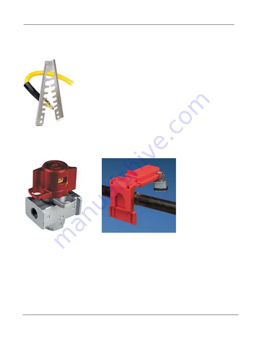
For  Compressed  air

If quick disconnects are used, disconnect the air lines at the disconnects.  These may be locked with  a

device like the following:

If a quick disconnect is not used, a lockable valve or locking device for  a non locking valve  should  be

use. Following are examples of these. The valve should vent the pressure when in the off position.

Summary of Contents for DRS27

Page 1: ...DRS27 ...

Page 2: ......

Page 3: ...emove panels of the crate 2 Remove all boxes from the crate 3 Remove the shipping boards holding the bridge and side wings 4 Remove the four bolts from the bottom two hold down boards 5 Place two 2 x 4 s onto the two forks of the fork lift to lift the machine out of the crate Be aware of the power cord and the CPU holder when locating the forks under the machine 6 Lift the machine above the suppor...

Page 4: ......

Page 5: ...iew Chapter 2 Unpacking Installations Facility Requirements Chapter 3 Machine Function Verifications Chapter 4 Software Overview Chapter 5 Process Development Guide Engineering Training Chapter 6 Templates Removal Site Clean Replacement Chapter 7 Operator Training Chapter 8 Maintenance Chapter 9 Schematics Appendix ...

Page 6: ...DRS27 User s Manual Table of Contents 0027 00 902 ...

Page 7: ...D PLACEMENT 7 1 4 4 MACHINE WARNING LABELS 7 1 4 5 DRS27 SYSTEM ALARMS 9 1 5 MACHINE OVERVIEW 10 1 5 1 FRONT PANEL CONTROLS 10 1 5 2 POWER START UP POWER DOWN CONTROLS 15 1 6 OPTIONS OVERVIEW 16 1 6 1 SITE CLEANING SYSTEM 0029 03 012 16 1 6 2 PIVOTING IR PROBE WITH LASER POINTER 0029 11 043 16 1 6 3 DIRECT VIEW CAMERA 17 1 6 4 UNIVERSAL INSERTION TOOL AU6LGA47R 17 1 6 5 PASTE ON DEVICE MICRO STENC...

Page 8: ...DRS27 User s Guide Chapter 1 Introduction Overview 0027 00 902 1 2 ...

Page 9: ...ment system aid in reducing operator required activity and providing a level of process control through partial automation 1 1 Contacts Support Air Vac is always willing to assist our customers with any technical or operating questions If you have any questions on machine parameters correct nozzle requirements options procedures or mainte nance please do not hesitate to call Air Vac Engineering Co...

Page 10: ...arranty Products cannot be returned to Air Vac without authorization please call for an RMA 1 3 Heating Element Limited Life Warranty Air Vac Engineering Company warrants the heating elements for a period of ninety 90 days from date of shipment Air Vac agrees to repair or replace any or all such equipment that may prove to be defective within the warranty period without expense excluding shipping ...

Page 11: ...wer from all machine functions and devices The PC and monitor will remain powered To reset rotate the EMO knob to unlatch Turn the key switch all the way to the right and release to restart Restart the DRS27 software Operator safety warning labels and markings are employed Gas nozzle handling tools has been included and should be used when handling hot nozzles 1 4 1 General Safety Machines and too...

Page 12: ... Use cau tion near heated surfaces including the nozzle and the bottom heater Hot surfaces are noted with labels but exposure to hazards is inevitable due to the nature of the process Do not touch hot surfaces Proper training is essential Contact Air Vac for additional train ing sessions if required Always use the gas nozzle handling tool when installing or removing nozzles The nozzle and vision s...

Page 13: ...l place the nozzle in a container that can handle the heat of the nozzle To install a nozzle reverse the above procedure 1 4 3 Label Description and Placement The following metal placards are affixed to the DRS27 system This label describes the electrical and air requirements for the system The overall system requirements can be found in the facilities section of this manual 1 4 4 Machine warning ...

Page 14: ...ermal danger to the operators This label indicates the presence of a Laser diode module with a Class 2 Laser Do not stare into the beam Direct viewing into the beam or reflected beam can cause permanent eye damage Po 1 mW _ 650 nm This label indicates the presence of an area that pre sents a pinch point hazard when motion occurs Keep hands and all objects clear of this area This label indicates th...

Page 15: ..._Restart DeviceIO_Communication_Restart Low_Pressure_Air_Regulator Low_Pressure_N2_Regulator Process Alarms Nozzle_Temperature_Limit Nozzle_TC_Error Left_Preheater_Temperature_Limit Left_Preheater_TC_Error Right_Preheater_Temperature_Limit Right_Preheater_TC_Error Center_Preheater_Temperature_Limit Center_Preheater_TC_Error Below_Minimum_Nozzle_Flow_Rate Nozzle_Flow_Sensor_In_Position_Failed Excee...

Page 16: ...DRS27 User s Guide Chapter 1 Introduction Overview 0027 00 902 1 10 1 5 Machine Overview 1 5 1 Front Panel Controls ...

Page 17: ...ide Chapter 1 Introduction Overview 0027 00 902 1 11 USB Port Start Switch Turns machine on off Power Light Indicates machine is turned on Lights Turns external lights on off Ground Upper Heater Flow Calibration Port ...

Page 18: ...ent camera con trol corners edge and center position ing Z axis nozzle control up down posi tioning Theta nozzle control clockwise counterclockwise positioning Zoom vision alignment camera magnifi cation control Rapid Used to select rapid function of joystick Default off When pressed joystick pilot light will be blinking Joy Stick Pilot Light Off Indicates joy stick is not active On Indicates joy ...

Page 19: ...erview 0027 00 902 1 13 Teach Inactive Nozzle Vacuum On Off Inactive Z Axis Indicates joy stick control of z axis Zoom alignment camera vision Indicates joy stick control of camera zoom Theta Nozzle Indicates joy stick control of nozzle rotation ...

Page 20: ...DRS27 User s Guide Chapter 1 Introduction Overview 0027 00 902 1 14 Nozzle Y Axis Adjustment Nozzle X Axis Adjustment Nozzle XY Axis Lock ...

Page 21: ...Start Up Power Down Controls Power Start Up 1 Turn on PC 2 Release E stop 3 Turn Power key on off switch 4 Boot software 5 Enter operator name Click on the Thumbs Up icon 6 Enter password Power Down 1 Exit DRS27 software 2 Turn off computer 3 Turn power key off E Stop Power Switch ...

Page 22: ...the composite vacuum tip to provide non contact site cleaning Notes Of Interest Non contact site cleaning will become critical for lead free rework due to the significantly higher temperature required to reflow the residual site solder Small medium and large composite vacuum tips provided Custom designs available for hard to access areas 1 6 2 Pivoting IR Probe with Laser Pointer 0029 11 043 Objec...

Page 23: ...ment or reflow at board level How it works Video is activated by operator or software Focus zoom lighting adjustments are made to optimize clarity The site image is integrated with the software and displayed on the PC monitor 1 6 4 Universal Insertion Tool AU6LGA47R Mechanically self centers any device for accurate pick up Used in conjunction with component shuttle ...

Page 24: ...ce Notes Of Interest Air Vac does not supply the component specific micro stencils Recommended supplier is Mini Micro Stencil 760 591 3804 Micro stencil installed into adapter for direct pick from shuttle 1 6 6 Flux Dip Pedestals part number quoted per device Stainless steel fluxing pedestals with precision machined depth provides controlled application of tacky flux directly to the solder spheres...

Page 25: ...e Extraction Manifold Hose Assembly 300 00 547 Objective Removes flux vapors from the work environment for operator health and safety Includes Fume extraction manifold and hose assembly Notes Of Interest Requires connection to a central exhaust or self contained filtering system ...

Page 26: ...DRS27 User s Guide Chapter 1 Introduction Overview 0027 00 902 1 20 ...

Page 27: ...ALLING THE BOTTOM HEATER 12 2 3 INSTALLING THE OPTIONAL BOTTOM SPOT HEATER 16 2 4 INSTALLING THE OPTIONAL DIRECT VIEW CAMERA 19 2 5 INSTALLING THE OPTIONAL IR SENSOR WITH FINE SPOT LASER POINTER 26 2 6 INSTALLING THE OPTIONAL PIVOTING IR SENSOR 28 2 7 INSTALLING THE OPTIONAL FUME EXTRACTION MANIFOLD 29 2 8 FACILITY REQUIREMENTS DRS27 30 2 9 PNEUMATIC CONNECTIONS TOP AND BOTTOM HEATER 32 2 10 OTHER...

Page 28: ...DRS27 User s Guide Chapter 2 Requirements and Installation 0027 00 902 2 2 ...

Page 29: ... 902 2 3 2 Unpacking Installations Facility Requirements 2 0 Unpacking from Crate Remove all boxes from crate Remove side table and support wings from crate Table Support Wings 2 Side Table with keyboard tray NOTE FOR 3 ZONE MACHINES THE WINGS ARE MOUNTED ON THE TABLE ...

Page 30: ...DRS27 User s Guide Chapter 2 Requirements and Installation 0027 00 902 2 4 Remove shrink wrap that s holding the X Y Z Axis in place ...

Page 31: ...DRS27 User s Guide Chapter 2 Requirements and Installation 0027 00 902 2 5 For spot heater equipped machines only cut off wire ties that are holding the spot heater to the car rier rail rods ...

Page 32: ...DRS27 User s Guide Chapter 2 Requirements and Installation 0027 00 902 2 6 Cut off wire ties holding the tubing and cables as shown ...

Page 33: ...DRS27 User s Guide Chapter 2 Requirements and Installation 0027 00 902 2 7 Cut off wire ties holding the spot heater to the bridge as shown ...

Page 34: ...DRS27 User s Guide Chapter 2 Requirements and Installation 0027 00 902 2 8 Cut off wire ties holding the spot heater to carrier ...

Page 35: ...DRS27 User s Guide Chapter 2 Requirements and Installation 0027 00 902 2 9 Cut off wire ties holding the vision X and Y axis as shown ...

Page 36: ...DRS27 User s Guide Chapter 2 Requirements and Installation 0027 00 902 2 10 2 1 Installing the Side Table Install the front and rear table support wings to the right side of frame 2 bolts each wing ...

Page 37: ...DRS27 User s Guide Chapter 2 Requirements and Installation 0027 00 902 2 11 Attach side table with keyboard tray to the support wings 4 bolts ...

Page 38: ... 0027 00 902 2 12 2 2 Installing the Bottom Heater Remove all bubble wrap covering the preheater Release brake located on the front panel and push x y axis to the rear of machine Lift carrier and prop up using kick stand A Locate preheater support blocks B A B ...

Page 39: ...to each corner of the preheater 2 front 2 rear C Position the four support blocks as shown in the photos so that the preheater is in its lowest possi ble position This is necessary for proper clearance for the spot heater The 41mm tall board sup ports are used with the preheater in the lowest position C C ...

Page 40: ...emove packing foam under preheater it is recommended to have two people perform this Lift front of heater and remove the two pieces of foam D Locate preheater onto the support blocks E NOTE The front right support F will locate with the dowel pin on the preheater D E F dowel pin ...

Page 41: ...er 2 Requirements and Installation 0027 00 902 2 15 Verify that the preheater is located on the other three support blocks in each of the 4 corners G Situate the blue tube as shown H on the right and left side of preheater H G ...

Page 42: ...DRS27 User s Guide Chapter 2 Requirements and Installation 0027 00 902 2 16 2 3 Installing the Optional Bottom Spot Heater Locate the spot heater and attach to the machine with four screws as shown ...

Page 43: ...rements and Installation 0027 00 902 2 17 Attach spot heater arm A to the heating element B NOTE Preheater must be in place before arm can be added Tighten screw C to lock the arm to the heater Connect thermocouple connectors D A B D C ...

Page 44: ...de Chapter 2 Requirements and Installation 0027 00 902 2 18 Install heat shield over heating element with 4 40 screws supplied E Attach protection bar to machine with two 1 4 20 screws supplied as shown bottom photo E ...

Page 45: ...quirements and Installation 0027 00 902 2 19 2 4 Installing the Optional Direct View Camera Trolley mounting bracket and cables front of machine as shown Locate camera arm pivot bracket A and mount with two screws supplied as shown A ...

Page 46: ...DRS27 User s Guide Chapter 2 Requirements and Installation 0027 00 902 2 20 Use wire clip to hold camera cables as shown Insert camera arm into pivot bracket ...

Page 47: ...DRS27 User s Guide Chapter 2 Requirements and Installation 0027 00 902 2 21 Locate camera assembly and attach to camera arm with thumb knob as shown Attach cable to clip ...

Page 48: ...DRS27 User s Guide Chapter 2 Requirements and Installation 0027 00 902 2 22 Route camera light ring cable up and through camera arm as shown Attach the ends of the camera light ring cables together ...

Page 49: ...DRS27 User s Guide Chapter 2 Requirements and Installation 0027 00 902 2 23 Route the Cat 5 camera cable up through the camera arm as shown Route Cat 5 cable down through camera arm and attach to camera ...

Page 50: ...User s Guide Chapter 2 Requirements and Installation 0027 00 902 2 24 Tie off cables as shown NOTE Leave enough of a service loop so camera can pivot without pulling on the wires Attach arm cover service loop ...

Page 51: ...DRS27 User s Guide Chapter 2 Requirements and Installation 0027 00 902 2 25 Attach lower arm cover NOTE Leave enough of a service loop so arm can pivot without pulling on wires service loop ...

Page 52: ...nstallation 0027 00 902 2 26 2 5 Installing the Optional IR Sensor with Fine Spot Laser Pointer IR probe arm A is shipped installed on machine with ball mount B and IR sensor connector C Locate IR probe D and mount to ball mount E as shown E D B C A ...

Page 53: ...ser s Guide Chapter 2 Requirements and Installation 0027 00 902 2 27 Install connector to the IR sensor and screw down nut Install strain relief grommet and lock nut to the end of the IR sensor Assembled view ...

Page 54: ...ments and Installation 0027 00 902 2 28 2 6 Installing the Optional Pivoting IR Sensor The IR Sensor option is installed by Air Vac prior to shipment No installation is required Laser Pointer to indicate area being monitored by IR Sensor ...

Page 55: ...DRS27 User s Guide Chapter 2 Requirements and Installation 0027 00 902 2 29 2 7 Installing the Optional Fume Extraction Manifold The Fume Extraction Manifold is installed by Air Vac prior to shipment ...

Page 56: ... psi 21 scfm intermittent Clean dry air non condensing source 1 4 18 NPT male fitting x 6 hose supplied Operating Notes IMPORTANT Electrical The DRS27 is supplied with either the above plugs or a disconnect box on the frame The plug or disconnect arrangement is the means to have the machine be locked in the Off position See Maintenance section for details of Lockout Tagout The Euro versions are to...

Page 57: ... more details Be sure the device can handle the required flows Environmental Temperature Range 5 C to 40 C Relative Humidity Not to exceed 50 Altitude Up to 1500m above sea level Physical Machine Operating Dimensions WxDxH DRS27 67 x57 x72 DRS27 6Z 82 x57 x72 Machine Weight DRS27 750 lbs est DRS27 6Z 1000 lbs est Monitor Dimension W x D x H 17 x 17 x 10 Monitor Weight 20 lbs Transportation When tr...

Page 58: ...ons must be done prior to powering on the DRS27 Upper Heater Pneumatics Connection A 1 8 27 NPT male fitting x 6 ft hose 1 4 diameter supplied Pressure Setting B 80 psi adjust as required C Air Nitrogen Consumption 3 cfm Other Pneumatics nozzle vacuum site cleaning vacuum board cooling option Connection D 1 4 18 NPT male fitting x 6 ft hose 3 8 diameter supplied Pressure Setting E 80 psi adjust as...

Page 59: ...on 0027 00 902 2 33 2 10 Other Connections Accessory Panel Power Computer and Monitor A Footswitch B Ethernet C USB D Cooling Chamber Air E Route cables from accessory panel and monitor through the hole in rear of table frame to hook up to computer A B C D E ...

Page 60: ...ion 0027 00 902 2 34 Adjust the computer holder 3 places up or down to accept the computer using Allen wrench sup plied and adjust thumb knob A from right to left Install computer into holder as shown and adjust as required then tighten adjustment screws A ...

Page 61: ... s Guide Chapter 2 Requirements and Installation 0027 00 902 2 35 CPU Connections Computer Power A CPU and Monitor are both powered with 220V from machine Machine Ethernet B Mouse and Keyboard C Monitor D A C B D ...

Page 62: ...ench Set All 12055 Probe Tip 3 De 29A3 Button Probe 3SBP100 Fitting 1 4 BA 9001 00 013 Tubing Cond SI 9001 15 018 Tubing 3 8 ID 9001 15 036 Clip Grounding 9002 01 065 Fuse 10 amp 9002 04 018 Fuse 4 amp 9002 04 033 Fuse 1 2 amp 9002 04 038 Fuse 12 amp 9002 04 055 Component Assy 9002 14 005 Board 28mm QFP 9002 14 017 Nozzle NT27EZ27 Box Plastic 9004 00 005 Case Plastic 9005 03 029 Anti Seize AS15 Fi...

Page 63: ...ne Function Verifications 3 Machine Function Verifications 3 3 0 VERIFICATION OVERVIEW 3 3 1 VOLTAGE VERIFICATION 4 3 2 PRESSURE VERIFICATION 6 3 3 FLOW RATE VERIFICATION AND ADJUSTMENT 7 3 4 NOZZLE HEATER TEMPERATURE VERIFICATION 13 3 5 VISION ALIGNMENT VERIFICATION AND ADJUSTMENT 22 ...

Page 64: ...DRS27 User s Guide Chapter 3 Machine Function Verifications 0027 00 902 3 2 ...

Page 65: ...rmance It is important that the verification procedures be done sequentially as outlined in this section Machine verification should be done After initial setup Anytime the system is physically moved or disconnected At regularly scheduled intervals such as every 3 4 months Verification processes are stored in a hidden menu to enter the hidden menu please do the following Right click on the Air Vac...

Page 66: ...p icon to advance to the next screen 7 Select thumbs again when prompted for the password system is shipped with no password 8 Machine will perform a Home Operation Click on OK 9 Using the right side mouse button click on the Air Vac logo on the screen main menu background color will change to red You are now in the Hidden setup window 10 Select Options from the menu bar 11 Select Open then Profil...

Page 67: ... begin the process 14 Verify that the machine voltage below left is between 205 and 220 volts while the process is run ning Voltage must not be below 205 volts See facility sheet regarding buck up transformer if the voltage drops below 205 volts 15 Each leg below right must be approximately 120 volts Cycle Start ...

Page 68: ...FOR THE ACCESSORY PORT IS 21 SCFM THE AIR CONSUMPTION FOR THE UPPER HEATER IS 3 SCFM IF AIR LINE IS COMBINED 24 SCFM MUST BE MAINTAINED AT 80 PSI INSUFFICIENT AIR SUPPLY LOW VOLUME DUE TO QUICK DISCONNECTS SMALL DIAMETER LINES OR ANY LINE RESTRICTION WILL CAUSE A PRESSURE DROP INSUFFICIENT AIR WILL RESULT IN PREMATURE HEATER DAMAGE AND OR PROCESS REPEATA BILITY ISSUES IN ADDITION TRANSFERRING PROF...

Page 69: ...roller which controls actual flow rates and the Nozzle Flow Sensor which controls the Computer Digital Flow Display Nozzle flow verification is required for initial installation or any time the machine is disconnected and or moved 3 3 1 Nozzle Flow Controller Verification and Adjustment Materials required Scribed reference flow meter supplied with the machine Initial conditions Pressure to upper h...

Page 70: ...tment Screen Log on as DRS27 or any high level security operator and select the Thumbs Up icon Using right side mouse button click the Air Vac logo You are now in the Hidden Setup window Select Setup Adjustments Nozzle Flow from the menu bar The Nozzle Flow Adjustment screen will appear as shown below ...

Page 71: ...re making any adjustments Check the 100 scribe line on the flow meter If the flow meter reads too high or too low adjust ments can be made immediately by dragging or clicking on the track bar within the Nozzle Flow Controller group box B The airflow should not be interrupted The adjustments will be automati cally applied and stable within 3 5 seconds The track bar is always connected to the active...

Page 72: ...ds too high decrease make 2 clicks on the left side of the track bar C If the flow meter reads too low increase make 2 clicks on the right side of the track bar C Once the 100 Flow Controller value has been set check flow controller verifications for 30 90 settings D With the nozzle flow system activated for the various settings check the flow using the meter Adjust the nozzle flow controller C as...

Page 73: ...ing any adjustments Check the blue meter that is being displayed on the left side software screen This meter repre sents the actual flow rate sensor output from the flow controller If the blue meter is too high decrease the value by making 2 clicks B on the left side of the track bar If the blue meter is too low increase the value make 2 clicks B on the right side of the track bar Retest for 30 90...

Page 74: ...RANGES 30 90 THE PURPOSE OF THIS STEP IS TO ASSESS THE OVERALL PERFORMANCE OF THE FLOW SYSTEM Select the Thumbs Up icon to save changes and exit the Flow Adjustment screen Disconnect the black hose and the flow meter Software Screen Flow Meter Target Value 30 30 scribe 82 scfm 40 40 scribe 1 10 scfm 50 50 scribe 1 37 scfm 60 60 scribe 1 65 scfm 70 70 scribe 1 92 scfm 80 80 scribe 2 20 scfm 90 90 s...

Page 75: ...NCAL 5 temperature verification nozzle into the machine Plug the nozzle thermocouple into channel 1 Temperature verification can be performed using the automatic verification utility available from the Setup menu Hidden level The user does not need to be involved in the calculation of these offset parameters the software will automatically determine the necessary adjustments during the process cyc...

Page 76: ...in the Compute Nozzle Offsets box A The box B will turn solid and the name will change to Apply Nozzle Offsets C Click on the green Cycle Start icon D to start the process Click on the blue box E to save the data after the process is complete Click on the Thumbs Up icon F A B C D E F ...

Page 77: ...DRS27 User s Guide Chapter 3 Machine Function Verifications 0027 00 902 3 15 Select Control Thermal Profile Analysis from the main menu ...

Page 78: ...DRS27 User s Guide Chapter 3 Machine Function Verifications 0027 00 902 3 16 Click on the green Open button A Select the latest Temperature Scale Testing Ncal 5 that you just ran A ...

Page 79: ...points should be plus minus 10 C of the 100 200 300 400 C set points If it is the Nozzle Heater Temperature Verification Process is complete If the green Ncal5 temperature is beyond plus minus 10 C of the 100 200 300 400 C set point at one or more of the four target points right click on the Air Vac logo to select the red hidden menu Re select Setup Adjustments Nozzle Heater from the main menu 100...

Page 80: ...cations 0027 00 902 3 18 The Compute Nozzle Offsets box A should have a check mark in it Click on the Green Cycle Start button B to automatically recalculate the nozzle offsets Click on the Blue box C after the process is complete to save the data A B C ...

Page 81: ...DRS27 User s Guide Chapter 3 Machine Function Verifications 0027 00 902 3 19 Select Control Thermal Profile Analysis from the main menu ...

Page 82: ...DRS27 User s Guide Chapter 3 Machine Function Verifications 0027 00 902 3 20 Click on the green Open button A Select the latest Temperature Scale Testing Ncal 5 that you just ran A ...

Page 83: ...r so that it points to the last few seconds of the chart at 100 C 200 C 300 C and 400 C The green Ncal5 temperature at the four points should be plus minus 10 C of the 100 200 300 400 C set points If it is the Nozzle Heater Temperature Verification Process is complete 100 C 200 C 300 C 400 C ...

Page 84: ...2 3 22 3 5 Vision Alignment Verification and Adjustment Vision Alignment Nozzle 1016 03 101 Vision Alignment Plate 1016 03 100 Load an unpopulated PCB into carrier Load Vision Alignment Nozzle into nozzle clamp Select Options Open Profile Open from the Red Restricted menu ...

Page 85: ... profile Thumbs Up to continue to run screen Click on the Green Cycle Start icon and follow prompts Shown is an image overlay of the Vision Alignment Nozzle and the Vision Alignment Plate Note that the black lines do not match up with the green lines This indicates that an adjustment to the Vi sion System is required ...

Page 86: ...ly see below Ad just the image so that the green lines are centered as shown If it is not possible to center the green lines as shown loosen the center lock screw slightly Make X Y adjustments as required and carefully tighten lock screw Y Axis adjustment screw Lock screw X Axis adjustment screw Run the Vision Alignment Profile a second time to verify that the alignment is now correct ...

Page 87: ... 1 4 Software Overview 4 Software Overview 3 4 0 WINDOWS TOOLS OVERVIEW 3 4 1 OPTIONS MENU FUNCTIONS 7 4 2 CONTROL MENU FUNCTIONS 21 4 3 HISTORY MENU 71 4 4 SETUP 73 4 5 RESET OPERATOR 77 4 6 CAMERA 78 4 7 CAMERA VIEWS 79 4 8 PROTECTED SYSTEM SECURITY ACCESS 82 ...

Page 88: ...DRS27 User s Guide Chapter 4 Software Overview 0025 00 902 4 2 ...

Page 89: ...27 Software Main Screen Buttons Icon buttons are generally used to activate a procedure or function Moving the cursor over the top of the icon and clicking on the left mouse button will initiate the button s functionality Button icons have a popup message that will tell the operator what the purpose of the button is this automatically occurs when the cursor is placed over the top of the icon Note ...

Page 90: ...rally used to program a DRS25 function or activity Inactive Clear state A blank check box indicates the Off or the inactive state Active Black state A black check mark indicates the On condition or the active state For Example The footswitch mode is activated The time mode and time delay value are not used Filled state A filled box indicates a third option For Example Clear Continue to Main Screen...

Page 91: ...hrough the list using the scroll bar to the right of the list box The operator can select any line within the list by moving the mouse to that line and clicking left button on that line To select an entry the operator can highlight the line click and then select the OK button Up Thumb The operator can also select an entry by double clicking on the line ...

Page 92: ... to display several lines of information on the screen After making a selection the list box collapses back down to one line For Example By clicking left button on the down arrow the board group list box will expand to show more of the possible choices The operator can select any line within the list box by simply clicking left mouse on that line The edit box will return to its original state with...

Page 93: ...DRS27 User s Guide Chapter 4 Software Overview 0025 00 902 4 7 4 1 Options Menu Functions View of the Options Menu ...

Page 94: ...e Options menu will automatically clear the current profile from memory and display the teach screen The system is ready to teach a new profile NOTE IT IS HIGHLY UNLIKELY THAT YOU WILL EVER NEED TO CREATE A NEW PROFILE FROM SCRATCH THE SAVE AS AND PROFILE BUILD FUNCTIONS ARE TYPICALLY USED AND ARE EXPLAINED LATER ...

Page 95: ... library organization The profile list can be adjusted by changing the group selection combination Clicking on the down arrow of a group list box will display a window with all the available options for that group Use the scroll bar to view any additional entries beyond those that are currently displayed To make a profile selection click on the desired entry File list box then click on the Ok butt...

Page 96: ...erator to the Open Profile Notes screen This screen is used to display general setup or process related information Clicking on the Ok button will take the operator to the Run screen Note HIGH PRIORITY USER HAS THE OPTION TO CLICK ON THE CONTINUE TO RUN SCREEN BOX TO ADVANCE TO THE MAIN MENU CLEAR BOX OR TEACH SCREEN FILLED BOX ...

Page 97: ...is screen allows the operator to process an application In general this screen provides the operator with messages heating and flow rate information thermocouple readings and the overall progress of the cycle Please see the Run screen section for detailed information ...

Page 98: ...g Desoldering A soldering desoldering link B allows the operator to quickly open a related profile soldering or desol dering without leaving the Run screen The Link Name is not automatically generated The Link Name identifies points to to a previously created profile with process related functionality Typically a soldering profile has the desoldering Short Name entered as the Link Name Link Name S...

Page 99: ...mer Board and Device Group These groups E allow profiles to be organized using a combination of customer board and device name New groups can be easily created see Setup Group Categorizing profiles by group can significantly improve the ability to find the correct application profile File Search These controls allow the user to interactively search for the necessary file links The group drop down ...

Page 100: ... new functionality of the profile The user has the option to move the new profile to a different group New link names can be added at any time Note THE ORIGINAL PROFILE REMAINS UNCHANGED AND COMPLETELY INTACT THE USER SHOULD BE CAREFUL NOT TO ALLOW EXACTLY A LONG NAME THAT ALREADY EXISTS THE SYSTEM WILL ALLOW IDENTICAL LONG NAMES TO EXIST IN THE PROFILE LIBRARY The Short Name will auto matically b...

Page 101: ...erview 0025 00 902 4 15 Delete Profiles restricted access The Delete Profile screen allows the user to delete files based on the Long Name similar to the Open option The user will be prompted before any files are removed Delete Profile Screen ...

Page 102: ...le s to be backed up B Select the profile s to be backed up one or more C Select the USB Memory Storage Device for the profiles to be backed up to Plug into computer D Click on the backup icon to backup Click on Ok when asked to continue The profiles have been copied The triangle icon allows all the profiles of the machine to be accessed regardless of Customer Board or Device group Select all prof...

Page 103: ...ed access The Restore option allows profile s to be restored from a USB Memory Storage Device Select the Restore source The files available for restore will appear Click the restore icon The profiles have been restored to the DRS27 in the appropriate customer board and device group ...

Page 104: ...e for moving profiles 1 Select a target profile or click on the select all profiles button 2 Highlight left single click profile long name s multiple selections allowed 3 Select a destination profile group 4 Click on perform move button Perform move button Select profile group Select all profiles button ...

Page 105: ...DRS27 User s Guide Chapter 4 Software Overview 0025 00 902 4 19 About DRS restricted access The About screen contains general information about the current software version ...

Page 106: ...RS27 system correctly Click on the Options menu and select the Exit option This will close the DRS27 software and shut down any active devices vacuum air flow etc The Windows Desktop screen will be displayed Click on the Windows icon menu located in the lower left corner of the screen Then click on Shutdown ...

Page 107: ...DRS27 User s Guide Chapter 4 Software Overview 0025 00 902 4 21 4 2 Control Menu Functions View of the Control Menu ...

Page 108: ...Process Events Programming Functions The Teach screen allows multiple Task Options to be processed in a single event The Task Options have programmable Task Properties to provide process flexibility The Task Options will be activated in order from the top to the bottom of the Task Options list All z axis motion for task option processes are based on Nozzle height Component height Board carrier hei...

Page 109: ...ozzle N27EZ27 Notes Install board with connector in front Process Notes Control Provides process information to the op erator This information is made available to the operator during the Run cycle Click on the Process Note Control Icon to access Process Notes Control screen Sets critical component and z axis set up parameters for all motion functions ...

Page 110: ...nes component height mm Nozzle Z Offset Defines nozzle height in relation to 66 mm standard nozzle For exam ple the standard EZ nozzle measures 62 5 mm The offset is 2 50 mm The standard site cleaning nozzle is 70 0 mm The offset is 4 00 mm Board Z Height Defines the board height If the board does not rest on the carrier i e assembly has a frame and board is raised then the height of the board in ...

Page 111: ...l not advance in run screen until operator presses the footswitch The time is limited to 10 minutes Msg Message box provide operator information for event on run screen Event Insertion Button The Insert event button allows the operator to temporarily add a new event in between two existing events The inserted event will be an exact copy of the current event The inserted event will be added ahead o...

Page 112: ...s motion Motor Z Hot Gas Motor T Hot Gas Motor Z Controls z axis Motor T Controls theta axis Motor On Off Icon Indicates z axis motor is active Motor Theta Icon Indicates theta motor is active In Motion Indicates z axis or theta motor is in use In Position Indicates z axis or theta motor is at the position Up Down Arrows Used to activate motor 1 Box Sets velocity of motor Blue Box Displays the pos...

Page 113: ...er vision system is activated The laser pointer message Locate Target Site Using Laser Pointer is then shown on the run screen The opera tor moves the laser pointer to the site and presses the footswitch The vision system retracts Task Properties Footswitch Allows laser light to be on until footswitch is depressed Delay sec Sets time mode and time for laser pointer to be activated during process P...

Page 114: ...sition Height mm Distance of nozzle in reference to board carrier position Velocity Speed of z axis 0 100 Theta Motor Move Function Rotates nozzle to shear bonded components from board Action Nozzle rotates clockwise theta move and counterclockwise theta move Can allow mul tiple cycles loop sequence loop attempts Task Properties Theta Move deg Nozzle rotates clockwise to set angle Theta Move deg N...

Page 115: ...y pass system is activated Ambient air flows through the nozzle by passing the heating element Generally used to cool component package and joints in the replacement program after peak reflow temperature is reached This minimizes controls the time from reflow 1 peak temperature to end of reflow 2 just below melting temperature Temperature º C Sets the upper heater temperature Wait For Heater In Po...

Page 116: ...ion Activates the stabilize function to heat or cool down to z axis head Stabilize Channel Nozzle Heater Stabilize Activates thermocouple attached to heater head Stabilize Temperature C 90 default Sets temperature heater head Go to up down prior to event time activated for heater Stabilize Delay sec 600 default Sets maximum time allowed for Stabilize Temperature to occur 600 second default allows ...

Page 117: ...ighFlow Board Cooling Task Properties Heater Any or all section 1 3 can be selected to be selected to be activated 1 in front Temperature ºC The temperature of the bottom heaters can be programmed from 0 350ºC Use LowFlow Board Cooling Turns on low flow air to cool board and or bottom heaters 3 cfm Use HighFlow Board Cooling Turns on high flow air to cool board and or bottom heaters 7cfm HotGas Te...

Page 118: ... the channel temperature When the board temperature is lower than the channel temperature the board cooling system will be off and the heaters reactivated Task Properties Heater Section 1 3 Activates the 3 sections of the bottom heater 1 in front Temperature º C Sets the bottom heater temperature for all sections selected Channel IR Manual TC01 TC08 Indicates and selects the IR temperature sensor ...

Page 119: ...is activated and the nozzle moves until it registers a force place target programmed The nozzle moves up depart height Task Properties Approach Height mm Sets the initial distance of the nozzle to the component Use Force Table Activates use of load cells force measurement of board carrier 50 2000g Place Target grams Sets force of nozzle against component to be reached prior to departure from compo...

Page 120: ...ves up de part height Task Properties Approach Height mm Position for nozzle to internally calibrate vacuum sensor Height is based on distance from board carrier Note Sufficient air passage is critical Use Vacuum Sensor Stop Stops downward movement based on vacuum change Pick Velocity Speed of nozzle moving down Safety Target gram Maximum force as backup Theta Move deg Nozzle will rotate clockwise...

Page 121: ... the board to internally calibrate vacuum sensor range of the site cleaning nozzle Note Sufficient air passage is critical Approach Height mm Sets initial distance of nozzle relative to board prior to process heating Initial Heating Delay Time nozzle heating is applied at the sensor approach height prior to x y operator movement of the site cleaning tip Note It is important that the residue solder...

Page 122: ...e of nozzle relative to board prior to process heating Initial Heating Delay Time nozzle heating is applied at the sensor approach height prior to x y operator movement of the site cleaning tip Note It is important that the residue solder be molten prior to vacuum control being applied The nozzle tip must seal to register a correct vacuum force measurement used in conjunction with the sensor initi...

Page 123: ...zle height component thickness and feeder tool thickness Incorrect informa tion can result in damage to the machine and or component Approach Height mm Sets the initial distance of the nozzle relative to the feeder tool platform Operator Load Feeder Tray Activates message on run screen for operator to load the component to the load feeder tray Use Vacuum Sensor Stop Activates use of nozzle vacuum ...

Page 124: ...vement is paused depart delay and then moves up depart height Task Properties Feeder Tool Height mm Sets the height of the feeder tool not active Approach Height mm Sets the distance the nozzle moves relative to the board carrier prior to the nozzle vacuum activated Depart Height mm The distance the nozzle moves after the nozzle vacuum is applied Depart Delay sec The time the between the nozzle go...

Page 125: ...ckness Incorrect information can result in damage to the machine and or component Approach Height mm Sets the initial distance of the nozzle relative to the feeder tool with the com ponent in place Use Vacuum Sensor Stop Activates use of nozzle vacuum sensor The nozzle vacuum is turned on and stops when the component seals against the nozzle o ring vacuum cup based on minimum in ternally set vacuu...

Page 126: ...ht Task Properties Dip Station Tool Height mm Sets height of dip station tool NOTE The dip station vision feeder motion is based on the nozzle height component thickness and feeder tool thickness Incorrect informa tion can result in damage to the machine and or component NOTE Measure the z height of the Dip Tray approx 6 25mm and subtract 1 0mm to obtain compression Approach Height mm Sets the ini...

Page 127: ...ED and magnification camera zoom Task Properties Top Vision LED Controls the intensity of the top LED for component leads viewing Bottom Vision LED Controls the intensity of the bottom LED for the top of the site board viewing Camera Zoom Controls magnification of the camera 1st Corner Vision System Sets the first position of the camera to the site based on the center of the laser pointer teach po...

Page 128: ...city Task Properties Approach Height mm Sets the initial distance of the component relative to the board Place Target gram Sets force of the component against the board to be reached prior to nozzle vacuum being turned off Place Velocity Speed nozzle moves component to board Vacuum Off Delay sec Time the nozzle vacuum is off after place target gram is reached Use Blow Off Air Activates air pressur...

Page 129: ...is typically the IR Sensor Function Wait TC sets the mode for one thermocouple usage Temperature ºC Sets the target temperature for the thermocouple to be reached Direction Sets the direction for the target temperature to be reached Increase mode is used for heating applications Decrease mode is used for cooling applications In Position Delay sec Sets the time the function is in use Normally not u...

Page 130: ...n screen to the camera screen The direct view camera camera direct view is turned on display status Task Properties Camera Direct View Determines camera to be activated direct view camera Display Status Turns on no check in box or off check in box camera Note Operator can switch back and forth from run screen to camera view screen at any event in the program when display status is on ...

Page 131: ...ice site clean vacuum is selected Status indi cates device is activated Task Properties Name Selects device for signal control Site Clean Vacuum Nozzle Vacuum Probe Vacuum Manual IR Probe Home Sensor Status Turn signal on or off Wait for Signal Can be used to delay signal control function if another device is activated Maximum Delay sec Allows delay of signal control for set time ...

Page 132: ...e height component thickness and reject bin tool thickness Incorrect information can result in damage to the machine and or component Approach Height mm Distance from component to reject bin Vacuum Off Delay sec Time nozzle vacuum is turned off after approach height is reached Use Blow Off Air Activates air pressure through nozzle vacuum o ring vacuum cup before nozzle retracts Uses blow off air d...

Page 133: ... Chapter 4 Software Overview 0025 00 902 4 47 General Image Image List Control Function Allows saved image or video to be displayed during an event of the program Action An image or video is saved using the camera screen ...

Page 134: ...are Overview 0025 00 902 4 48 The camera screen will appear 1 Select Direct View or Vision System Camera A 2 For photo click Save Camera Video image icon For video click Start Video Stop Video icons 3 Name image in Save Video file box A ...

Page 135: ...DRS27 User s Guide Chapter 4 Software Overview 0025 00 902 4 49 4 Close Screen 5 Go to Teach Screen and select Photo Video for any event s of program to be displayed ...

Page 136: ...DRS27 User s Guide Chapter 4 Software Overview 0025 00 902 4 50 6 Saved Photo Video will be shown in Run Screen in Support Options ...

Page 137: ... removal procedures Foot switch control and Alarm conditions Event messages and temperature plotting graphically show the progress of a cycle The Cycle Start Stop button is used to activate or terminate the process cycle This button will display a green background when the cycle is active or a gray background when the cycle is not active Clicking on this button when the background is green will te...

Page 138: ...tware alarms 1 Machine Hardware Alarms 2 Process Alarms Machine Hardware Alarms This alarm type occurs when one of the following conditions is detected SerialPort_Failure Z_Axis_Motor_Comm_Restart Vision_Axis_Motor_Comm_Restart Nozzle_TempControl_Comm_Restart Left_Preheat_TempControl_Comm_Restart Right_Preheat_TempControl_Comm_Restart Center_Preheat_TempControl_Comm_Restart DeviceIO_Communication_...

Page 139: ...eheater_TC_Error Right_Preheater_Temperature_Limit Right_Preheater_TC_Error Center_Preheater_Temperature_Limit Center_Preheater_TC_Error Below_Minimum_Nozzle_Flow_Rate Nozzle_Flow_Sensor_In_Position_Failed Exceeded_Max_FootSwitch_Delay Exceeded_Max_TC_Control_Delay TC1_Not_Connected TC2_Not_Connected TC3_Not_Connected TC4_Not_Connected TC5_Not_Connected TC6_Not_Connected TC7_Not_Connected TC8_Not_...

Page 140: ...een setup by the process engineer The operator cannot access these notes while a cycle is active In the Teach Screen notes can be provided for the operator In addition vital object nozzle and board dimensions are stored and set The Profile Note Screen is activated when the program is selected prior to the Run Screen The object nozzles and board dimensions are not shown to the operator ...

Page 141: ...screen is organized into the following sections Numeric Process Information Profile Event Alert Foot Switch Messages Graph Process Information Event Time Event Counter Process Time Button Functions Software Hardware Communication Link Error Status Bar Code Board Serial Number Tracking Menu Functions ...

Page 142: ... process temperature flow rate force and thermocouples Nozzle and Preheater System The Nozzle System upper heater graphically displays the following control parameters Nozzle flow rate percentage set point A yellow needle Nozzle flow rate actual percentage B blue needle Nozzle target temperature set point C green number Nozzle actual temperature D red number B A A C D ...

Page 143: ...er positioned between the set point and actual displays When a thermocouple channel is controlling the process a yellow T C Control A message will be displayed at the bottom of the screen This message will define the type of thermocouple activity and the temperature target A real time display offers the current temperature of all thermocouple channels B Note ALL ACTIVE THERMOCOUPLE CHANNELS MUST B...

Page 144: ...ated with component force placement force re moval or force adjustment The Force System graphically displays the following control parameters Force target set point green A Force actual applied force red B A B Note DURING ANY FORCE CONTROLLED ACTIVITY PLACEMENT REMOVAL ADJUSTMENT THE OPERATOR SHOULD NOT TOUCH ANY PART OF THE MACHINE ...

Page 145: ...nt and Foot Switch Messages B This section of the Run screen displays system foot switch messages or pre programmed event alert messages Messages are used to inform the operator when machine interaction is required or to com municate the general progress of the profile cycle B ...

Page 146: ...Information C This section of the Run screen displays the Temperature vs Time graph Event Time D Time remaining in the current event Event Counter E Current and maximum profile event counters Process Time F Total overall cycle time all events is plotted on the chart display D E F ...

Page 147: ...DRS27 User s Guide Chapter 4 Software Overview 0025 00 902 4 61 Function Buttons G This section of the Run screen displays the function buttons that are available to the operator G ...

Page 148: ...un screen and return the operator to the Main screen Nozzle Vacuum The Nozzle Vacuum button will activate or deactivate the nozzle vacuum When this function is active the button background will be display in green Nozzle Device Separation Blow Off The Device Nozzle Separation button will activate a small volume of air back through the nozzle vac uum tube helps to separate the component from the no...

Page 149: ...hts This button will turn on the lights of the Z axis Board Cooling High Low Flow Rate This button will activate toggle through the available board cooling flow rates low high and off Home All Motors This button will home all Z and Vision motor axis Direct Vision Lights option This button will turn on the lights of the direct view camera option ...

Page 150: ...e Cleaning Vacuum The Site Cleaning Vacuum button turns the Site Cleaning Vacuum on and off Laser Pointer Teach Position Activates the Laser Pointer in the Vision Housing to teach the component location Dry Run Activating this will allow the profile to run without heat ...

Page 151: ...ode Board Serial Number Tracking I This section of the Run screen allows a board serial number to be tracked and recorded in the cycle history file The operator has the option to enter this information using the standard keyboard or to use the optional bar code scanner I ...

Page 152: ... that are available to the operator Load Process Link File Menu Option The Load Process Link File menu J allows the operator to toggle between the soldering desolder ing and site cleaning profiles This allows related profiles to be cycled without leaving the Run screen This menu option is only available when the process is not cycling J ...

Page 153: ... folder Clicking on the small blue button K will export the chart data to the export folder Export directory C Program Files Air Vac Engineering DRS27 Export Run This information can be retrieved at a later time using the Thermal Profile Analysis utility A help message will inform the operator that the graph data was successfully saved K ...

Page 154: ...zed and stored using an 8 digit file sequence number Clicking on the green button will present a file browse window allowing the operator to select chart data files from one of the following folders C Program Files Air Vac Engineering DRS27 Export Run C Program Files Air Vac Engineering DRS27 Export Tutor Clicking on the red button will toggle the display from line graphics to a to data point tabl...

Page 155: ...icking on Control Thermal Profile Analysis Printing will display the following screen Clicking on the green button will present a file browse window allowing the operator to select chart data files from one of the following folders C Program Files Air Vac Engineering DRS27 Export Tutor Or C Program Files Air Vac Engineering DRS27 Export Run Click on the File to analysis ...

Page 156: ... reviewed such as maximum joint temperature maximum package tem perature time over set temperature etc To change set temperature input desired temperature in box To view specific slopes move vertical bars Clicking on the red button will toggle the display from line graphics to a data point table ...

Page 157: ...s Guide Chapter 4 Software Overview 0025 00 902 4 71 4 3 History Menu The History menu has two options Cycle and Alarm Cycle History A History file entry is recorded each time the operator cycles a process profile ...

Page 158: ...Chapter 4 Software Overview 0025 00 902 4 72 Alarm History The software continuously monitors the controlling sub systems If an alarm condition occurs for any process or hardware issue an Alarm file entry will be recorded ...

Page 159: ...ters These options are only available to high priority operators Preheater Idle Selecting the Preheater Idle from the Setup menu will present the operator with the Preheater Idle Control screen These settings are global and will control the preheater during all screens except the Run screen Individual profiles will control the preheater based on process requirements ...

Page 160: ... type the desired group name into the group edit box A Click on the New Add Entry button to insert the new group into the existing list B To delete a group the operator must first highlight the group Next the operator can click on the Delete Highlighted Entry button C to remove the entry from the list To save these changes click on the Thumbs Up button To cancel any changes click on the Thumbs Dow...

Page 161: ...apter 4 Software Overview 0025 00 902 4 75 Limits and Defaults This screen is used is primarily used to modify the default profile groups used by the Open profile option The process temperature limits are for reference only ...

Page 162: ... all screens Caution should be taken when defining these operators All critical machine parameters or process profiles can be adjusted Low priority Operator Operators can only run existing profiles and are not allowed to make process adjustments The password edit boxes are used is used to enter modify verify the password associated with each operator priority level Users can have different machine...

Page 163: ...Overview 0025 00 902 4 77 4 5 Reset Operator Click on the Reset Operator Log Off option on the menu bar and the Operator Login screen will be displayed Log in again followed with your security access code to gain access to the DRS27 machine ...

Page 164: ...the Camera screen will be displayed The screen is to access the Vision System or Direct View option camera The Camera screen will automatically be displayed when the Alignment Motion Object Alignment Board Carrier Inspection Inspection Board Car rier or Inspection Inspection Direct View box in the teach screen is activated ...

Page 165: ...stem or inspection direct view It can also be manually activated on the run screen 4 7 1 Vision System Component Alignment The camera screen will normally be activated automatically during the component replacement process It is programmed in the Inspection block Inspection Vision System The message Locate Target Site Using Laser Pointer will be shown on the run screen Then the camera screen will ...

Page 166: ...automatically in the direct view mode The direct view mode can be activated manually in the run screen and using pull down menu activated The DRS27 lights are turned on off by the z axis lights icon The camera lights are turned on off by the camera light icon 4 7 3 Direct View Camera Reflow View The direct view camera can be utilized to view solder reflow ...

Page 167: ...e Cleaning The direct view camera can provide close up view of the site cleaning process The z height position can be adjusted using the site clean up down arrows The vacuum sensor of the site cleaning program will continue to automatically ad just based on the new settings ...

Page 168: ...System Security Access To access the Protected System Menu the user must click on the Air Vac logo with the right mouse button The menu background color will change to red The menu options will be changed to allow ac cess to machine calibration and critical properties parameters ...

Page 169: ...DRS27 User s Guide Chapter 4 Software Overview 0025 00 902 4 83 The Protected System Security Menu consists of Options Control History Setup Reset Operator ...

Page 170: ... User s Guide Chapter 4 Software Overview 0025 00 902 4 84 Camera Options functions are the same as in the main menu Control functions are the same as in the main menu History function includes Machine Tasks ...

Page 171: ...lity as the standard operator idle option Selecting the Preheater Idle from the Setup menu will present the operator with the Preheater Idle Control screen These settings are global and will control the preheater during all screens except the Run screen Individual profiles will control the preheater based on process requirements ...

Page 172: ...s are set for each air flow percentage reference and calibrated to a certified flow meter The Flow Sensor and Flow Con troller have individual dial indicators and are adjusted individually starting at 100 Slide bars make adjustments easier and only the target flow rate that is currently being change this re duces accidental adjustment to different flow rate parameters ...

Page 173: ...ter 4 Software Overview 0025 00 902 4 87 Force Adjustment This screen is used to provide adjustment and calibration to the force system This activity is performed at the factory and normally does required customer adjustments ...

Page 174: ...vidual calibration points should not be made Adjustments are available to influence the automatic adjustment decision logic contact Air Vac fac tory technicians To start the calibration sequence the operator need only plug the NCAL 5 nozzle into thermocouple channel 1 and click on the start button The cycle will run for 25 35 minutes All necessary offsets are automatically computed Click the up th...

Page 175: ...operties All machine properties control setup parameters are connected to this screen Machine properties associated with different peripherals to be quickly adjusted Click on the plus sign to expand a category Use caution before making any critical machine control properties ...

Page 176: ...pter 4 Software Overview 0025 00 902 4 90 Machine Maintenance This screen offers access to all machine the interface control signals This screen is normally used to test individual control signals diagnose a repeatable issue ...

Page 177: ...ment Guide Engineering Training 3 5 0 PROFILE TUTOR SOFTWARE 3 5 0 1 OVERVIEW 4 5 0 2 PHYSICAL SETUP 4 5 0 3 CREATING A THERMAL PROFILE 6 5 0 4 TUTOR SCREEN THERMAL ANALYSIS 28 5 0 5 RUNNING A SECOND THERMAL CYCLE 29 5 0 6 THERMAL PROFILE RECORD KEEPING 31 5 0 7 PROFILE BUILD 34 5 0 8 PROGRAM EXECUTION 40 5 0 9 DIRECT VIEW CAMERA SOFTWARE SCREEN LIVE VIEW 43 ...

Page 178: ...DRS27 User s Guide Chapter 5 Process Development Guide Engineering Training 0027 00 902 5 2 ...

Page 179: ...uide Chapter 5 Process Development Guide Engineering Training 0027 00 902 5 3 5 Process Development Guide Engineering Training 5 0 Profile Tutor Software Access to Profile Tutor requires high operator password level ...

Page 180: ...Vac for further instructions Position the IR Sensor on an open area of the board 2 3 inches away from the rework site TC 1 Joints Slide a TC underneath the BGA and plug into channel 1 If possible slide two additional TC s under neath the BGA for additional data For large components 3 thermocouples will provide a good set of data to insure accurate profiling Erroneous TC s can be removed while runn...

Page 181: ...DRS27 User s Guide Chapter 5 Process Development Guide Engineering Training 0027 00 902 5 5 Thermocouple Ports ...

Page 182: ...DRS27 User s Guide Chapter 5 Process Development Guide Engineering Training 0027 00 902 5 6 5 0 3 Creating a Thermal Profile From the toolbar select Control then Profile Tutor Profile Tutor screen shown ...

Page 183: ...nt Guide Engineering Training 0027 00 902 5 7 1 Select double click the appropriate Thermal Profile Master that most closely matches the new ap plication The selected Master will load and the Template steps will appear under the Events column below ...

Page 184: ... length of the nozzle in mm and subtract from 66 Enter the difference o Nozzle length 66 Nozzle Z Offset NOTE All EZ style nozzles are 63 5 mm long 63 5 66 2 5 For all EZ style nozzles enter 2 5mm Enter Board Z Height thickness in mm IMPORTANT Entering the correct object component nozzle and board parameters is criti cal for proper z axis positioning Incorrect data can result in the nozzle con tac...

Page 185: ...See Addendum at back of this section for use and explana tion of Direct View Camera screen Force Place always put a check in this box Allows nozzle to ap proach then force touch top of component Depart Height Distance of nozzle from component top after Force Place during heating cooling events Use 2 0mm Start Board Additional development runs are typically necessary after the first iteration This ...

Page 186: ...pment Guide Engineering Training 0027 00 902 5 10 The events are shown The master profile name will be displayed at the top of the page All master profiles typically have seven 7 stages Events Preheat Presoak Soak Ramp Reflow 1 Reflow 2 and Off ...

Page 187: ...ide Engineering Training 0027 00 902 5 11 The Update All buttom offers the ability to quickly update all events to the set value in that single event Can be used for Preheater Temperature Spot Heater Temperature Nozzle Flow Rate and Event Trig ger TC s ...

Page 188: ...nd of soak to the beginning of reflow 5 REFLOW 1 Time over liquidus until the heaters are shut off 6 REFLOW 2 Time until the joints fall back below liquidus 7 EVENT Turns off the heaters The following are typical time temperature targets for each stage Event Tin Lead Lead Free PREHEAT Topside Board Temp C 90 120 130 150 avg 100 avg 140 PRESOAK Joint Temp C 101 139 141 169 Time seconds 20 45 20 45 ...

Page 189: ...than 10mm 30 10 15 mm 35 40 16 26 mm 45 50 27 31 mm 55 60 32 35 mm 65 36 40 mm 70 75 40 mm 80 NMX Nozzles 40 60 Be sure to change the flow in all events except Preheat click on each event radio button to access the event flow rate The update all buttons offer the ability to quickly up date all the events based on the current event set tings NOTE The flow rate in the preheat event will change when ...

Page 190: ...d to for subsequent events to a level that maintains board top side temperature NOTE Preheater can be raised to a maximum of 350 C during preheat for high thermal mass assem blies Spot Heater If the Spot Heater option is installed on the system this section can be ad justed C to set the spot heater temperature for each event and if low flow or high flow should be enabled The default setting is 325...

Page 191: ...ving across the surface The programmer has the option to 1 Keep the air flow of the upper heater low for example 30 to reduce the air current cooling ef fect This method will allow the system to have to stable repeatable initial conditions prior to the remaining heating events 2 Turn off the upper heater no air flow or temperature during the preheat event This event may allow the board to preheat ...

Page 192: ...Stage in the Events list and check mark the channel s being used to control joint temperatures during process If only one TC is monitoring joint temperature the T C 1 box should be checked as shown above If three TC s are monitoring joint temperature T C 1 2 and 3 boxes all should be checked Click on the Update All TC Triggers box ...

Page 193: ...00 902 5 17 Initializing Process Development Run Install the EZ Nozzle that matches the component size or is slightly larger than the component NOTE If the EZ Nozzle is smaller than the component heating uniformity will be poor Click on the Move To Laser Pointer Teach Position icon ...

Page 194: ...housing will move outward and the laser pointer will activate Position the bottom spot heater near the center of the bottom heater plate Move the z head using the blue ring so the red laser dot is roughly centered on the spot heater Install the board so the laser pointer is also centered on the component ...

Page 195: ...ng 0027 00 902 5 19 Lock the carrier arms and tighten the hold down clamps Position board supports if necessary Install the joint thermocouple s and plug in to channel 1 2 3 Click on the icon Use the Laser Pointer to position the IR sensor 2 3 inches away from the compo nent ...

Page 196: ...and the laser pointer teach position red dot will activate The laser should already be centered on the component The vision system will retract when you click on the yellow footswitch message The nozzle will then move downward and touch the component under force control and will retract the programmed height C NOTE If the nozzle is not centered over the component use the x y wheels to correct this...

Page 197: ...in Lead profile Time is not used as this is a temperature based event using the IR probe The Presoak Event will continue until T C 1 or multiple checked TC s if used reaches 169 C Lead Free profile or 139 C Tin Lead profile Time in Presoak stage is automatically recorded and saved If one thermocouple is providing an erroneous reading it may eliminated from the event by clearing the box ...

Page 198: ...k Event will continue until T C 1 reaches 200 C Lead Free profile or 165 C Tin Lead pro file Time in Soak stage is automatically recorded and saved The Ramp Event will continue until T C 1 reaches 216 C Lead Free profile or 182 C Tin Lead pro file Time in Ramp stage is automatically recorded and saved ...

Page 199: ...s 245 C Lead Free profile or 215 C Tin Lead profile Time in Reflow 1 stage is automatically recorded and saved The Reflow 2 Event will continue until T C 1 drops down below 217 C Lead Free profile or 183 C Tin Lead profile Time in Reflow 2 stage is automatically recorded and saved NOTE Total time over reflow is the sum of Reflow 1 and Reflow 2 ...

Page 200: ...Upper Heater Off Event 0 seconds IMPORTANT If the Event Trigger temperature is not being reached in a reasonable amount of time 30 sec onds in Presoak and Ramp 60 seconds in Soak and Reflow1 click on the Nozzle Temperature tab and drag it to the right so that the temperature increases by 25 degrees ...

Page 201: ...DRS27 User s Guide Chapter 5 Process Development Guide Engineering Training 0027 00 902 5 25 A new Event A will be inserted automatically and the nozzle temperature will increase to the new set point A ...

Page 202: ...ser s Guide Chapter 5 Process Development Guide Engineering Training 0027 00 902 5 26 If you stop A the Thermal Profile you must click on the green Home Vision System icon B before you restart the process A B ...

Page 203: ...rofile Common naming protocals include as sembly name component type and size tin lead TL or lead free LF nozzle used and creation date creator initials Click on red green icon to save Confirmation of save WARNING If you exit Tutor without saving the graph the process information will be lost 11002 DRS 27mm BGA lead free Alpha Board 052215 BPC 11002 DRS 27mm BGA lead free Alpha Board 052215 BPC ...

Page 204: ...me ranges you have created a good thermal profile Proceed to the Profile Build section If the Soak and or Reflow stage s are less than the minimum target of 45 seconds the profile is too hot and has run too fast If the Soak and or Reflow stage s are greater than the maximum target of 75 seconds the profile is too cold and has run too slow NOTE High thermal mass components on high thermal mass asse...

Page 205: ...e first run as a result of an on the fly adjustment should be deleted prior to starting additional tutor cycles NOTE The Event Trigger temperature must be reset Procedure for deleting an added event 1 Highlight the target event left single click 2 Right double click on the arrow event will provide a delete message 3 Click the ok button to accept complete the delete activity ...

Page 206: ...ature by 25 degrees in the Presoak Soak Ramp Reflow 1 stages if the Soak and or Reflow 1 stages are longer than 75 seconds Increasing the Nozzle temperature will speed up the profile and reduce the time in each event Click on the Start icon A Machine will automatically cool board and heater head to restart tem perature then re run process Name and save the second run recommended same name as first...

Page 207: ...ineering Training 0027 00 902 5 31 5 0 6 Thermal Profile Record Keeping After a new thermal profile is created the thermal profile is saved The Thermal Profile Analysis tool is used for documentation and reference to analyze the profile Click on the green icon ...

Page 208: ...lopment Guide Engineering Training 0027 00 902 5 32 Insure that you are looking in the Tutor folder Path to data is C Program Files Air Vac Engineering Platform Export Tutor Double click on the thermal profile that you just created to open it ...

Page 209: ...sition first yellow bar C1 where T C 1 is 170C second yellow bar C2 where T C 1 is at 200C Soak stage C3 should be 45 75 seconds ok 60 seconds Reflow Joints D should have time above 217C of 45 75 seconds ok 57 and 58 seconds Confirm max joint temperature E was approximately 240C ok 241 235 Maximum package temperature should not exceed 260 ok 248C The thermal profile can be printed F for permanent ...

Page 210: ...Build Now that a good thermal profile has been created and saved for the new application the Automatic Profile Build function is used to integrate the new thermal profile into a complete rework process that enables the user to remove site clean and replace the new component Select Control Build Profile Build ...

Page 211: ...r Masters radio button E and select the appropriate Master Templates which will be displayed in the four boxes F Select create the profile groups G where you want the profile to be saved to Name the new profile H NOTE A good way to create the profile name is to copy the tutor results name and paste it in the Profile Name box Check the Use box I The Object Nozzle Board dimensions J should automatic...

Page 212: ...DRS27 User s Guide Chapter 5 Process Development Guide Engineering Training 0027 00 902 5 36 Enter set up notes for the application J Select the Thumbs Up Exit icon K to save K J ...

Page 213: ...DRS27 User s Guide Chapter 5 Process Development Guide Engineering Training 0027 00 902 5 37 Select the thumbs up icon L to save Click OK M to continue file save L M ...

Page 214: ...layed in the directory you specified in Profile Build Desoldering Automatic component removal using the thermal profile you developed excluding cooling Site Cleaning Removal of residual site solder after component removal Soldering Component replacement using the thermal profile you developed includ ing cooling Thermal The thermal profile you created but with time based events ...

Page 215: ...DRS27 User s Guide Chapter 5 Process Development Guide Engineering Training 0027 00 902 5 39 ...

Page 216: ...rocess Development Guide Engineering Training 0027 00 902 5 40 5 0 8 Program Execution Four new profiles should now be available Desoldering Site Cleaning Soldering and Thermal are automatically appended to the file name you created ...

Page 217: ...velopment Guide Engineering Training 0027 00 902 5 41 Double click on the Desoldering profile to open it The process notes page is then displayed for the operator Click Thumbs Up to continue to the Run screen after reviewing the setup notes ...

Page 218: ...raining 0027 00 902 5 42 The profile name A will be displayed at the top of the page Select Cycle Start B to start the profile Follow all prompts After the component is removed select Load Process Link File C for site cleaning Exe cute and reiterate for soldering A C B ...

Page 219: ...View Access the Tutor Camera screen after starting a Tutor Run A by clicking on the Camera option B in the top left corner of the main Tutor screen then choose Open If the Use Camera checkbox C was checked during setup prior to starting a Tutor Run the system will automatically go directly to the Camera screen after starting Tutor A A B C ...

Page 220: ...clicking D Assign a name for file in E then click F to choose a location to store file G Adjusts height of Site Clean tool above site NOTE This feature is not active in Tutor only active during the site cleaning process H Takes the Z Axis to the home position I Turns the Direct View Camera light ring on and off J Turns the Nozzle vacuum on and off K Turns the Pickup Probe vacuum on and off L Turns...

Page 221: ...pter 6 Templates Removal Site Clean Replacement 0027 00 902 6 1 6 Templates Removal Site Clean Replacement 6 Templates 3 6 0 OVERVIEW 3 6 1 REMOVAL TEMPLATE 3 6 2 SITE CLEAN TEMPLATE 15 6 3 REPLACEMENT TEMPLATE SOLDERING 25 ...

Page 222: ...DRS27 User s Guide Chapter 6 Templates Removal Site Clean Replacement 0027 00 902 6 2 ...

Page 223: ... the Build function is used to create complete desoldering site cleaning and soldering profiles The events in these templates are explained and documented in this section 6 1 Removal Template Select Options Open Profile Open Select the Customer Board Device Group where the new profile was saved Highlight the desoldering profile and click on the thumbs up icon to proceed ...

Page 224: ...DRS27 User s Guide Chapter 6 Templates Removal Site Clean Replacement 0027 00 902 6 4 Select TeachProcess in the Continue To pull down box The nozzle heater is turned on to stabilize the hot gas head ...

Page 225: ...DRS27 User s Guide Chapter 6 Templates Removal Site Clean Replacement 0027 00 902 6 5 This event will continue until the hot gas head thermocouple reaches 90 C The nozzle heater is then shut off ...

Page 226: ...hapter 6 Templates Removal Site Clean Replacement 0027 00 902 6 6 The Laser Pointer Teach is used to locate the component The operator is instructed to position the IR sensor The bottom heater and spot heater are activated ...

Page 227: ...DRS27 User s Guide Chapter 6 Templates Removal Site Clean Replacement 0027 00 902 6 7 The nozzle force touches the component and retracts the programmed distance A The direct view camera activates ...

Page 228: ...Guide Chapter 6 Templates Removal Site Clean Replacement 0027 00 902 6 8 The laser pointer on the IR temperature sensor is activated The operator is prompted to position the IR sensor The nozzle heater is activated ...

Page 229: ...er s Guide Chapter 6 Templates Removal Site Clean Replacement 0027 00 902 6 9 The bottom heater and spot heaters are activated The board is preheated to 140 C from the thermal profile developed in profile tutor ...

Page 230: ...6 Templates Removal Site Clean Replacement 0027 00 902 6 10 The nozzle heater setting and time from the presoak stage in the thermal profile The bottom heater and spot heater settings from the presoak stage in the thermal profile ...

Page 231: ... s Guide Chapter 6 Templates Removal Site Clean Replacement 0027 00 902 6 11 Soak stage time and nozzle heater settings from the thermal profile Bottom and spot heater soak stage settings from the thermal profile ...

Page 232: ...uide Chapter 6 Templates Removal Site Clean Replacement 0027 00 902 6 12 Ramp stage time and nozzle heater settings from the thermal profile Ramp stage bottom heater and spot heater settings from the thermal profile ...

Page 233: ...oval Site Clean Replacement 0027 00 902 6 13 Automated component removal using the vacuum sensor NOTE The Reflow 1 cooldown stage from the thermal profile was automatically deleted in the build function Nozzle heater off after component removal ...

Page 234: ...DRS27 User s Guide Chapter 6 Templates Removal Site Clean Replacement 0027 00 902 6 14 Bottom and spot heaters off Direct view camera off ...

Page 235: ...DRS27 User s Guide Chapter 6 Templates Removal Site Clean Replacement 0027 00 902 6 15 6 2 Site Clean Template Select Options Open Profile Open Highlight the Site Cleaning profile Thumbs up to proceed ...

Page 236: ...Chapter 6 Templates Removal Site Clean Replacement 0027 00 902 6 16 Select TeachProcess from the pull down menu Use the Laser Pointer Teach to locate the component Position the IR sensor 2 3 inches away from the component ...

Page 237: ...DRS27 User s Guide Chapter 6 Templates Removal Site Clean Replacement 0027 00 902 6 17 Bottom and spot heaters on IR probe laser on ...

Page 238: ...er s Guide Chapter 6 Templates Removal Site Clean Replacement 0027 00 902 6 18 Operator prompted to Install SC Nozzle Test vacuum and Position Direct View Camera Bottom and spot heater on Direct view camera on ...

Page 239: ...DRS27 User s Guide Chapter 6 Templates Removal Site Clean Replacement 0027 00 902 6 19 Site cleaning nozzle vacuum on Nozzle heater on Operator prompted to flux site ...

Page 240: ...DRS27 User s Guide Chapter 6 Templates Removal Site Clean Replacement 0027 00 902 6 20 Preheating board to 120 C Bottom ans spot heater temperatures reduced after board reaches 120 C ...

Page 241: ...e Chapter 6 Templates Removal Site Clean Replacement 0027 00 902 6 21 Force touch and retract of site clean vacuum tip Site clean nozzle retracts Operator prompted to reflux site for second pass cleaning or stop process ...

Page 242: ...DRS27 User s Guide Chapter 6 Templates Removal Site Clean Replacement 0027 00 902 6 22 Second pass force touch and retract of site clean vacuum tip Nozzle moves to park position ...

Page 243: ...DRS27 User s Guide Chapter 6 Templates Removal Site Clean Replacement 0027 00 902 6 23 Site clean nozzle heater cool down Board cool down ...

Page 244: ...Guide Chapter 6 Templates Removal Site Clean Replacement 0027 00 902 6 24 Site clean nozzle heater off Operator prompted to remove site clean nozzle and install EZ nozzle for component replacement soldering process ...

Page 245: ...RS27 User s Guide Chapter 6 Templates Removal Site Clean Replacement 0027 00 902 6 25 6 3 Replacement Template Soldering Select Options Open Profile Open Highlight Soldering process Thumbs up to continue ...

Page 246: ...DRS27 User s Guide Chapter 6 Templates Removal Site Clean Replacement 0027 00 902 6 26 Change pull down list to TeachProcess ...

Page 247: ...DRS27 User s Guide Chapter 6 Templates Removal Site Clean Replacement 0027 00 902 6 27 Bottom heater and spot heater on low temperature Nozzle heater activated for stabilization ...

Page 248: ...er s Guide Chapter 6 Templates Removal Site Clean Replacement 0027 00 902 6 28 Stabilization continues until the head thermocoouple reaches 90 C If the head thermocouple is above 125 C nozzle cooling will turn ...

Page 249: ...C NOTE The head thermocouple will be at a high temperature at the end of the site cleaning process If a soldering process is run immediately after site cleaning cooling of the head will take time Cooling down the head is important for thermal repeatability The nozzle heater is shut off after heating cooling of the head to the target temperature is complete ...

Page 250: ... Clean Replacement 0027 00 902 6 30 The Laser Pointer Teach Position is activated and the operator is prompted to locate the component The IR probe laser activates and the operator is prompted to position the IR probe 2 3 inches away from the component ...

Page 251: ...operator verifies component polarity and places the device in the universal insertion tool The insertion tool is loaded in the component pickup station at the front of the vision housing Settings for the top and bottom LED lights camera zoom and initial corner view in vision during alignment ...

Page 252: ...nt is complete the vision retracts and the operator is prompted to flux the site NOTE Tacky flux should be used to hold the component in place and to improve wetting Automatic force placement of the component and retract of the nozzle NOTE Do not touch machine during this event as it may create a false force trigger and drop the part ...

Page 253: ...Replacement 0027 00 902 6 33 Reflow 2 cooling the component down from maximum temperature to below liquidus will then execute The Preheat Presoak Soak Ramp Reflow 1 stages from the thermal profile same as in the desoldering profile will run Nozzle cooling off ...

Page 254: ...DRS27 User s Guide Chapter 6 Templates Removal Site Clean Replacement 0027 00 902 6 34 Board cooling off Head to park position ...

Page 255: ...DRS27 User s Guide Chapter 6 Templates Removal Site Clean Replacement 0027 00 902 6 35 Nozzle cool down Board cool down ...

Page 256: ...DRS27 User s Guide Chapter 6 Templates Removal Site Clean Replacement 0027 00 902 6 36 Direct view camera off Process complete ...

Page 257: ...FILE 3 7 0 OVERVIEW BGA REMOVAL SITE CLEANING SOLDERING 3 7 1 POWER UP LOG IN 4 7 2 MAIN SCREEN OVERVIEW 6 7 3 OPEN A TYPICAL PROGRAM 9 7 4 INSTALL NOZZLE 11 7 5 RUNNING A TYPICAL REMOVAL PROGRAM 15 7 6 RUNNING A TYPICAL SITE CLEANING PROGRAM 21 7 7 RUNNING A TYPICAL SOLDERING PROGRAM 30 7 8 REFERENCE RUN SCREEN OPERATOR CONTROLS 41 ...

Page 258: ...DRS27 User s Guide Chapter 7 Operator Training 0027 00 902 7 2 ...

Page 259: ...dering Program 1 Remove site cleaning nozzle with handling tools and install component nozzle 2 Follow message prompts WARNING The DRS machine is configured to run on the dedicated PC provided The custom software is configured for optimum machine performance in conjunction with the Windows operating system Additional software loaded may affect performance and system integrity The pc is not intende...

Page 260: ...ight next to the key will illuminate Turn PC on and let it boot up to the Administrator screen Click inside the black Air Vac box The administrator password is AirVac Double click on the AV DRS27 icon to start the software The Operator Registration screen will appear Enter your operator name and click on Thumbs Up If access is denied contact supervisor ...

Page 261: ... a password and click on the Up Thumb icon to continue If access is denied consult supervisor NOTE Operator Names and Passwords must be correct to access software Low priority will only allow access to minimal screens The machine is shipped with operator and no password under low priority limited access Machine will perform a home operation remove nozzle and click OK ...

Page 262: ...erator Training 0027 00 902 7 6 7 2 Main Screen Overview Note Using the low priority password limits the operator access to computer screens and restricts parameters from being changed This allows all profiles to be run as programmed ...

Page 263: ...Operator Training 0027 00 902 7 7 Options Open Profile Open The programs are opened and executed A file directory will be shown listing all created programs In that directory change the directory to open and execute other programs ...

Page 264: ...TWARE Control Run Process Activates screen to run the program This screen is automatically displayed after a program is opened and the Open Profile screen is presented Reset Operator Allows a new operator to log on Note IT IS GOOD PROCEDURE TO PRESS RESET OPERATOR WHEN LEAVING THE MACHINE THIS PREVENTS UNQUALIFIED PERSONNEL FROM USING THE MACHINE UNDER THIS OPERATOR S NAME PROGRAMS AND OPERATOR NA...

Page 265: ...Options then Open Profile Open will present the Open Profile All Listings Screen Select Group The operator must select the correct Customer Board and Device Group directory Using the Up Down Arrows at the right side of the each group box to select a BGA file Select Program Under files highlight a program file Click on Thumbs Up icon ...

Page 266: ...s the device to be reworked For example PBGA 425 35mm Lead Free Location Describes location and board For example U3 on Aqus Board Flux Type Describes the flux to be used For example Kester 2331 NC Tacky Flux Tool The nozzle used For example N35EZ35EB Notes Saves helpful information about the assembly Provides operator tasks and checks prior to running the program Prior to going to the Run Screen ...

Page 267: ...DRS27 User s Guide Chapter 7 Operator Training 0027 00 902 7 11 7 4 Install Nozzle Install the nozzle relatively square into the nozzle fingers with pliers supplied ...

Page 268: ...DRS27 User s Guide Chapter 7 Operator Training 0027 00 902 7 12 Prior to starting the Removal Process click on the Move to Laser Pointer Teach Position icon ...

Page 269: ...the Bottom Heater plate and the Laser is centered over the Spot Heater plate Reinstall the board so that the Laser Pointer is also centered on the component to be reworked Tighten the hold down clamps and position board supports if necessary These two steps insure that both the Spot Heater and Nozzle are in the correct location Click on the yellow footswitch message to retract the laser and vision...

Page 270: ... position the IR Sensor prior to starting the process Click on the Toggle IR Probe Laser Pointer icon The icon will turn green and the Fine Spot Laser Pointer will illuminate Position the laser dot approximately 2 3 inches away from the BGA on an open area of the board ...

Page 271: ...ram consists of a number of steps or events The Message Box will change for each event to provide instructions The information on the screen is only for recording to a history file The operator is not responsible for process development Temperatures times and air flow settings cannot be changed on this screen ...

Page 272: ...DRS27 User s Guide Chapter 7 Operator Training 0027 00 902 7 16 Click on the green and white bullseye to start the process ...

Page 273: ...027 00 902 7 17 Event 1 Stabilizing Hot Gas Head It is important from a thermal repeatability standpoint to condition the tempearture of the hot gas head prior to running a process Event 1 stabilizes the hot gas head to a minimum temperature of 90 C ...

Page 274: ...r will activate and should already be centered on the component Footswitch to continue The Laser Pointer and Vision Housing will retract automatically The Nozzle will move to the near place position The Force System will control the Nozzle touch off of the component The Nozzle will retract the programmed distance ...

Page 275: ...NE BOARD PREHEATING TARGET TEMPERATURE MAY BE PROGRAMMED DIFFERENTLY FOR VARIOUS ASSEMBLIES Events 4 7 Presoak Soak Ramp Reflow 1 There is no operator involvement during these events The programmed heating of the BGA is automatic Theses are timed events based on previous thermal profiling The time for each event is displayed at the bottom of the screen The time counts down for each event The progr...

Page 276: ...ccidental hitting of previously removed components The component is dropped onto the tray in front of the vision system The vision system and nozzle retract At the end of the process the operator has three options Select the Load Process Link File for the site cleaning Press the Start Cycle icon to start another removal cycle Press Thumbs Up icon to exit the screen ...

Page 277: ... Site Cleaning Program select the Application Notes icon The Open Profile Note screen will appear It provides information prior to running the program It is important that the site cleaning nozzle be clean See Maintenance Section Select the Cycle Start Stop icon to begin the site cleaning program Process Hints Running the site cleaning program immediately after the removal program will take advant...

Page 278: ...r Position laser pointer to left rear corner of site This is advised to view solder reflow before moving site tool tip Position IR Sensor 2 3 inches from site using the Fine Spot Laser Footswitch to continue Event 2 Install Site Cleaning Nozzle and Test Vacuum Position Direct View Camera Install nozzle with vacuum port of nozzle to vacuum port of DRS27 ...

Page 279: ...s Guide Chapter 7 Operator Training 0027 00 902 7 23 Position direct view camera to view site on screen Camera Adjustments Aperture adjusts the lighting Zoom adjusts the magnification Focus adjusts the focus A B C ...

Page 280: ... timed event 75 seconds with the nozzle being heated during this time as the operator applies flux Apply flux paste generously over the entire site IMPORTANT The nozzle must heat soak prior to positioning at the board level This will allow the heat of the tool to be efficiently applied to the pads when lowered ...

Page 281: ... will heat the board until the set programmed temperature is reached NOTES Board preheating time will vary depending on the initial temperature of the bottom heater board and machine Board preheating temperature may be programmed differently for various assemblies During this step there is no operator involvement The bottom heater heats the board until the set programmed temperature is reached Pre...

Page 282: ...solder The nozzle tip height will adjust after touching the board to right above the pads The operator uses the X Y wheels to clean the site NOTE If the site solder does not reflow immediately during the tip s initial touch stop the process and contact a supervisor The tip will adjust according to programmed settings The distance from the bottom of the tip to the board may be different on various ...

Page 283: ...process cycle The site clean slide bar A can be used to raise or lower the auto height position If the nozzle tip is too close to the board move the slide bar slowly upwards until the overall position is optimized If the nozzle is bouncing to far from the board not collecting enough solder move the slider bar slowly downwards until the overall position is optimized A ...

Page 284: ...ite clean functions Camera open close Toggle IR probe laser pointer To move site clean tip up down adjust the slide bar in the Site box Machine light Camera light If the direct view camera option is not installed the site clean tip up down adjustment slide bar is on the run screen ...

Page 285: ...heated air will melt the solder The time will vary depending on board The nozzle tip height will adjust to right above the pads The operator uses the x y wheels to clean the site Event 8 Board and Machine Cool Down There is no operator involvement in this event The nozzle goes to the park position and the nozzle heater is set at a low temperature to cool down Event 9 Remove Site Clean Nozzle CAUTI...

Page 286: ...selected the profile name at the top of the Run Screen will change to the Soldering Program To review the Application Notes for the Soldering Program select the Application Notes icon The Open Profile Note screen will appear It provides information prior to running the program Select the Cycle Start Stop icon to begin the soldering program ...

Page 287: ...is a footswitch based event Install nozzle with handling tool Square nozzle as best as possible Footswitch to continue CAUTION NOZZLE AND OR MACHINE MAY BE HOT Event 2 Stabilize Hot Gas Head The hot gas head will be heated up to 90 C if the machine is cold or cooled to 110 C if the machine is hot ...

Page 288: ...ure Sensor The IR sensor is meant to read the board temperature It is important to position the sensor approximately 2 3 inches away from the component on an open area of the board Event 3 Align Component After Pick Up Insert the new component into the Universal Insertion Tool and center the component Install the Insertion Tool into the Component Pick Up Tray Footswitch to continue IMPORTANT Compo...

Page 289: ...DRS27 User s Guide Chapter 7 Operator Training 0027 00 902 7 33 The nozzle picks up the component from the pick up tray The nozzle and component retract The vision alignment system is activated ...

Page 290: ...DRS27 User s Guide Chapter 7 Operator Training 0027 00 902 7 34 The vision system camera screen is activated If pad and lead image is not clear use focus adjustment A on side of vision system A ...

Page 291: ...nsity of board B can be used Most likely the component will be skewed To correct for theta use the joystick The joystick has two functions available theta and camera zoom The joystick also has two speeds slow and rapid Pressing the rapid button sets the joystick functions in the fast mode To correct for theta move the joystick left or right To change the magnification move the joystick up or down ...

Page 292: ...he component until it is parallel to the pads and off in the y direction as shown below Move the x axis wheel to align leads and pads in x direction and the y axis wheel to align in y direction Increase magnification with the joystick to enhance alignment accuracy One corner of the BGA is now aligned ...

Page 293: ...orner light under Vision The light will turn green and the opposite corner will be shown If the opposite corner is aligned check the other two corners and center If the opposite corner is off in theta make a 50 theta adjustment and then finalize X Y Check the opposite corner and reiterate until both corners are aligned ...

Page 294: ... Component Nozzle Board Dimensions set by programmer C Toggle z axis LED light turns lights over the nozzle on and off D Toggle Nozzle Vacuum turns nozzle vacuum on and off E Stop All Process Activity stops all movement and heating F Camera Open Close opens and closes camera screen to toggle from camera to run screen F E B A A Component Corner being Viewed ...

Page 295: ...BGA will be lowered to board using force placement system of machine Nozzle vacuum is turned off Slight pressure through the nozzle is applied The nozzle retracts the programmed distance NOTE OPERATOR MUST NOT TOUCH MACHINE IF MACHINE SENSES PRESSURE ON THE BOARD CARRIER IT WILL AUTOMATICALLY GO TO THE NEXT EVENT THE NOZZLE VACUUM WILL BE TURNED OFF AND THE COMPONENT WILL BE DROPPED OUT OF ALIGNME...

Page 296: ...om left of the Run screen Event 12 Reflow 2 There is no operator involvement during this event The heating events are finished Cool air will be controlled through the nozzle and the board cooling system This is a timed event based on the programmer Event 13 Heaters Off There is no operator involvement during this event The preheater and upper heater are turned off Event 14 Machine and Board Cooldo...

Page 297: ...DRS27 User s Guide Chapter 7 Operator Training 0027 00 902 7 41 7 8 Reference Run Screen Operator Controls Laser Pointer Teach Position Start Cycle Stop Cycle ...

Page 298: ...erform rapid cooldown The nozzle cooldown involves a bypass operation to deliver cool air directly into the nozzle chamber does not cool down the heating element LED Light On Off machine lights Home Vision Systems Motors Brings nozzle top position and vision system rear position to home position Direct View Camera Lights On Off Site Cleaning Vacuum On Off IR Probe Laser Pointer On Off light Applic...

Page 299: ... actual temperature of preheat panels 1 front 2 middle 3 rear Bottom Hot Gas Spot Heater Indicates set and actual temperature of spot heater Force Indicates force and actual setting of force system Noz Htr Stblz Indicates temperature of thermocouple attached to hot gas head Manual IR Thermocouples Indicates temperature of IR temperature sensor Dry Run When activated runs program without heat param...

Page 300: ...apter 7 Operator Training 0027 00 902 7 44 Wait For Footswitch In footswitch events the operator can advance the program to the next event by clicking on Wait For Footswitch or by depressing the footswitch under the machine ...

Page 301: ...DRS27 User s Guide Chapter 8 Maintenance 0027 00 902 8 1 8 Maintenance 8 0 MAINTENANCE 3 8 1 GENERAL CAUTIONS 3 8 2 PREVENTATIVE MAINTENANCE SCHEDULE 4 8 3 LOCKOUT TAGOUT 5 8 4 ASSEMBLY DIAGRAMS 9 ...

Page 302: ...DRS27 User s Guide Chapter 8 Maintenance 0027 00 902 8 2 ...

Page 303: ...king on the machine If tasks do not require power perform proper Lockout Tagout procedures to ensure machine is safe to work on Note heaters may still be hot for some time after removing power If machine is required to be powered for maintenance tasks use caution Removal of covers ex poses high voltage areas Provide warnings to others in the area of exposed hazards Moving axis produce a pinch poin...

Page 304: ...th in case of flux use flux remover X Vision Unit Clean the protective cover glass on the lower and on the upper side of the vision unit Kimwipes Denatured Alcohol X Pneumatic Unit Inspect and drain the air regulator filters of any water or oil as required verify the air pressure is 0 55 mba X Vacuum Filter Replace vacuum filter if vacuum is insufficient to hold component See instructions in Maint...

Page 305: ...agout If servicing of the machine does not require power perform proper lockout tagout procedures Examples of devices for this are shown below for power and compressed air For power Use a lockout device similar to the one shown in Figure 1 For a standard size plug use HUBBELL P N HLDMP as shown in Figure 1 The cable shown in Figure 1 is a molded power cable used as an exam ple Figure 1 Lockout Dev...

Page 306: ... power connector into the device see Figure 2 Close the lockout device and slide the cover so that the padlock holes are lined up between the cover and the base see Figure 3 view A Insert a padlock see Figure 3 view B Figure 2 Insert Power Connector into Lockout Device Figure 3 Close Lockout Device and Attach Padlock ...

Page 307: ...nd Remove Keys Notes More than one padlock can be used For different power plugs other lockout devices are available from HUBBELL The standard plug uses P N HLDMP Bigger power plugs may use P N HLD or even HLD2 avail able from HUBBELL For more information go to http www hubbellcatalog com wiring To reenergize the unit Follow the above steps in reverse order ...

Page 308: ... used disconnect the air lines at the disconnects These may be locked with a device like the following If a quick disconnect is not used a lockable valve or locking device for a non locking valve should be use Following are examples of these The valve should vent the pressure when in the off position ...

Page 309: ...DRS27 User s Guide Chapter 8 Maintenance 0027 00 902 8 9 8 4 Assembly Diagrams ...

Page 310: ...DRS27 User s Guide Chapter 8 Maintenance 0027 00 902 8 10 ...

Page 311: ...1 pc 200 01 891 Gewindestange 3 1 pc 200 01 892 Druckstück 4 1 pc 200 01 923 Anschlagblech 5 1 pc 200 02 107 Halter 301 16 pc 100 00 021 Cyl Screw M3x20 BN3 302 4 pc 100 00 027 Cyl screw M4x6 BN3 303 2 pc 100 00 032 Cyl screw M4x16 BN3 304 4 pc 100 00 166 Lens head Screw M5x12 BN1593 305 2 pc 100 04 002 Washer M4 BN 726 306 1 pc 101 26 003 Turning knob M5x10 BN14176 307 0 6 m 109 19 032 Conduit pi...

Page 312: ... class Article number Article description 1 1 pc 200 01 089 Huelse Encoder 2 1 pc 200 03 390 Cover z axis 3 1 pc 200 01 155 Abdeckung Rueckwand 4 1 pc 200 01 156 Segment 23 5 1 pc 200 01 157 Segment 29 6 1 pc 200 01 166 Motorplatte Z 7 1 pc 200 01 408 Wellrohranschluss 29 8 1 pc 200 01 430 Abschlussplatte 9 1 pc 200 01 432 Attachment plate motor 10 1 pc 200 01 433 Mutterflansch 11 1 pc 200 01 435 ...

Page 313: ...c 100 02 019 Stellmutter Kuso MRR M6x0 5 314 2 pc 100 05 027 Cyl pin d 3 h6 x8 316 4 pc 100 05 040 Cyl pin d 4 h6x12 BN 858 317 1 pc 100 05 095 Federkeil 2x2x6 BN 870 318 1 pc 3 101 18 002 Z axis break 86621 03H00 24V 319 1 pc 3 101 22 007 Ball bearing 4 10 4 320 1 pc 3 101 22 033 Axial bearing ZKLR 0624 2Z 321 1 pc 2 101 28 006 Power grip belt GT 2MR 112 6m 322 4 pc 3 102 00 012 Linear bearing MN...

Page 314: ...Parts Lists 32 2009 Infotech AG Company confidential For internal use at OEM customers only 1 6 300 01 034 X Z Axis 230mm ONYX 25 OBC 70mm Initial date 15 05 2006 CL Change index 0 19 09 2008 AG ...

Page 315: ...0 01 892 Druckstück 4 1 pc 200 01 923 Anschlagblech 5 1 pc 200 02 107 Halter 301 8 pc 100 00 022 Cyl Screw M3x22 BN 3 302 4 pc 100 00 027 Cyl screw M4x6 BN3 303 2 pc 100 00 032 Cyl screw M4x16 BN3 304 4 pc 100 00 166 Lens head Screw M5x12 BN1593 305 2 pc 100 04 002 Washer M4 BN 726 306 1 pc 101 26 003 Turning knob M5x10 BN14176 307 0 65 m 109 19 032 Conduit pipe PMARobot PCSG 23B 50 601 1 pc 300 0...

Page 316: ...x 1 05 02 2009 MH Pos Amount Unit Spare part class Article number Article description 1 1 pc 200 01 089 Huelse Encoder 2 1 pc 200 01 156 Segment 23 3 1 pc 200 01 157 Segment 29 4 1 pc 200 01 166 Motorplatte Z 5 1 pc 200 01 367 Vertikalschlitten 6 1 pc 200 01 368 Deckel Rueckwand 7 1 pc 200 03 391 Haube Z Achse hoch 8 1 pc 200 03 385 Distance plate 9 1 pc 200 01 408 Wellrohranschluss 29 10 1 pc 200...

Page 317: ...x8 BN1593 313 4 pc 100 00 206 Threaded pin M3x6 with peak BN29 314 1 pc 100 02 019 Stellmutter Kuso MRR M6x0 5 315 2 pc 100 05 027 Cyl pin d 3 h6 x8 316 2 pc 100 05 040 Cyl pin d 4 h6x12 BN 858 317 2 pc 100 05 039 Cyl pin d 4 h6 x10 BN 858 318 1 pc 100 05 095 Federkeil 2x2x6 BN 870 319 1 pc 3 101 18 002 Z axis break 86621 03H00 24V 320 1 pc 3 101 22 007 Ball bearing 4 10 4 321 1 pc 3 101 22 033 Ax...

Page 318: ...re part class Article number Article description 1 1 pc 200 01 912 Achsverlängerung links 2 1 pc 200 01 913 Achsverlängerung rechts 3 1 pc 200 01 914 Abdeckhaube Onyx 25 301 3 pc 100 00 158 Lens head screw M3x8 BN1593 302 4 pc 100 00 180 Threaded Pin M4x4 BN 28 303 2 pc 101 26 003 Turning knob M5x10 BN14176 304 1 pc 2 109 51 006 Warning label 25 x 25mm hot surface 601 1 pc 300 01 006 Advanced sold...

Page 319: ...6 1 pc 200 01 235 Kabelhalter 7 1 pc 200 01 236 Steckerhalter 8 1 pc 200 01 259 Düsenkopf Drehkörper 9 1 pc 200 01 260 Klemmring 10 2 pc 200 01 261 Luft Vacuumrohr 11 1 pc 200 01 403 Support head Z axis 12 1 pc 200 01 404 Motorflansch 301 2 pc 100 00 014 Cyl screw M3x5 BN3 302 2 pc 100 00 017 Cyl screw M3x10 BN3 303 4 pc 100 00 017 Cyl screw M3x10 BN3 304 1 pc 100 00 035 Cyl Screw M4x25 BN 3 305 8...

Page 320: ...l date 21 03 2007 EG Change index 0 29 01 2009 AG Pos Amount Unit Spare part class Article number Article description 1 1 pc 200 03 256 Lampenhalter 2 2 pc 200 03 328 Unterlage 301 4 pc 100 00 023 Cyl Screw M3x25 BN 3 601 2 pc 300 01 422 Lamp adjustable 602 1 pc 300 01 479 Y Cable field illumination 603 1 pc 300 00 910 Cable field illumination ...

Page 321: ... Amount Unit Spare part class Article number Article description 1 1 pc 200 01 228 LED Gehaeuse 2 1 pc 200 03 263 Lampengehäuse 301 2 pc 100 00 016 Cyl screw M3x8 BN3 302 1 pc 100 00 015 Cyl screw M3x6 BN3 303 2 pc 100 00 159 Lens head screw M3x10 BN1593 304 2 pc 100 09 004 U Scheibe 3 2 7x0 5 BN670 rostfrei 305 0 2 ml 115 14 012 Loctite 270 10ml Gew Sich hochfest 601 1 pc 3 300 00 433 Illuminatio...

Page 322: ...n Initial date 20 02 2007 WB Change index 0 04 02 2009 MH Pos Amount Unit Spare part class Article number Article description 1 1 pc 200 01 179 Keil 2 1 pc 200 01 180 Zahnstange X 3 1 pc 200 01 200 Haltewinkel X Motor 4 1 pc 200 01 202 Motorstuetze X 5 1 pc 3 200 02 490 Transport safety lock Vision Y 301 8 pc 100 00 014 Cyl screw M3x5 BN3 ...

Page 323: ...G1 307 2 pc 102 00 017 Linearfuehrung Schiene MN 9 135 G1 V1 308 1 pc 3 109 04 028 Inductive sensor IWFM 18U7504 S35A 309 1 pc 109 04 029 Kabeldose ESG 32AH0200 4Pol 310 16 pc 100 00 013 Cyl Screw M3x4 BN 3 601 1 pc 300 00 454 Mechanical stop X complete 602 1 pc 300 00 501 Robotic cable vision motors 603 1 pc 300 00 564 Distance block vision system 604 1 pc 3 300 00 819 Gear motor Vision X 605 1 p...

Page 324: ... 1 pc 200 01 025 Handrad Objektiv 3 2 pc 3 200 01 131 Protection glass 4 1 pc 200 01 184 Zahnradgehaeuse 5 1 pc 200 01 186 Grundplatte Vision 6 1 pc 200 01 187 Bodenplatte 7 1 pc 200 01 188 Seitenplatte links 8 1 pc 200 01 189 Seitenplatte rechts 9 2 pc 200 01 190 Frame protection glass 10 2 pc 200 01 191 LED Abdeckring 11 1 pc 200 01 193 Objektivgehaeuse 12 1 pc 0027 17 102Grundplatte Zoomantrieb...

Page 325: ... BN 11 313 8 pc 100 00 208 Lens head screw M4x6 BN1593 314 2 pc 100 03 014 Zyl Schraube mit Schlitz M3x4 BN 330 315 2 pc 100 04 023 Washer M3 BN 715 316 1 pc 100 05 040 Cyl pin d 4 h6x12 BN 858 317 0 025 m 3 106 17 002 Polyurethane tube d 6mm black 318 1 pc 3 108 00 013 FireWire camera DFK 21F04 319 1 pc 3 108 01 004 Macro zoom objective Computar MLH 10X 320 1 pc 3 108 06 010 Tele converter 2x wit...

Page 326: ...isma 3 1 pc 200 01 930 Drehlager 4 2 pc 200 01 931 Klemmplatte Prisma 5 1 pc 200 01 932 Justierschraube Y 6 1 pc 200 01 933 Nocken 7 1 pc 200 01 934 Justierschraube X 301 5 pc 100 00 016 Cyl screw M3x8 BN3 302 1 pc 100 00 233 Gew Stift M5x40 BN28 303 1 pc 100 05 070 Zyl Stift d 6 h6 x30 BN 858 304 1 pc 100 12 016 Druckstueck M8x16 BN 13364 305 1 pc 2 101 20 024 O Ring di 3 s 1 Normatec 306 1 pc 3 ...

Page 327: ...de 3 1 pc 200 02 451 Kabelbride Platte 301 28 pc 100 00 016 Cyl screw M3x8 BN3 302 4 pc 100 00 046 Cyl screw M5x16 BN3 303 2 pc 100 00 126 Countersunk screw M3x10 BN21 304 2 pc 100 00 017 Cyl screw M3x10 BN3 305 2 pc 100 05 042 Cyl pin d 4 h6 x16 306 2 pc 102 00 022 Linear guiding rail MN 9 275 G1 V1 307 4 pc 109 19 007 Spacer M3 l 6 35mm 601 1 pc 3 300 00 568 Motor vision Y axis 602 1 pc 3 300 00...

Page 328: ......

Page 329: ...DRS27 User s Guide Chapter 9 Schematics 0027 00 902 9 1 9 Schematics 0027 00 900 DRS27 3 Zone Preheater 0027 21 900 DRS27 6 Zone Preheater ...

Page 330: ...DRS27 User s Guide Chapter 9 Schematics 0027 00 902 9 2 ...

Page 331: ...AC POWER PANEL POWER SUPPLY PANEL N AC NEUTRAL 114 103 105 117 113 24VDC Estop 24ret AC cont 62 11 21 13 260 60 176 61 59 55 54 58 52 115 53 116 105 104 116 53 115 52 13 21 11 98 84 90 96 89 83 97 85 17 62 83 98 97 85 179 178 177 84 98 97 85 83 96 179 178 177 179 178 177 177 17 178 179 96 83 85 97 98 84 207 208 207 209 208 210 209 211 212 78 213 82 219 1 2 1 2 104 105 84 89 90 96 89 90 60 260 61 1...

Page 332: ......

Page 333: ...5 LH3 TC LH3 TC LH2 TC LH2TC LH1TC LH1 TC TB26 TB27 TB23 UH TC UH TC TB28 TB29 CH GND HEAT HEAT T C T C 0100 01 120 2000W element plug K TC 1 1 2 2 TBL 3 Nozzle Heater 2000 Watts 220 V TB32 Head Assembly 0027 11 041 AC AC DC DC SSR2 AC AC DC DC SSR4 AC AC DC DC SSR3 AC AC DC DC SSR1 UH220V HOT UH220V RET Bottom Front HOT Bottom Front RET Bottom Back HOT Bottom center RET Bottom Center HOT Bottom B...

Page 334: ......

Page 335: ...LM N L NO C OP2 NO C OP1 TC TC PTA COM TX2 TX1 GN BK R BACK PREHEAT TEMPERATURE CONTROLLER LH1 TC LH1 TC R Y LH2 TC LH2 TC R Y LH3 TC LH3 TC R Y OPTIONAL 3rd HEATER 79 131 130 80 129 81 214 205 178 181 179 182 181 184 182 185 184 187 185 188 187 418 188 419 164 165 166 161 162 163 160 159 158 1 2 3 192 157 154 Temp Controller N Temp Controller L 1 2 3 4 5 6 7 8 UH NO UHC A LH1 NO LH1 C LH2 NO LH2 ...

Page 336: ......

Page 337: ...be Home Switch 10 30 VDC OUT 0 V 1 black 2 blue 3 brown Z Axis Home Switch 1 black 2 blue 3 brown Theta Home Switch 1 black 2 blue 3 brown Vision X Home Switch 1 black 2 blue 3 brown Vision Y Home Switch 10 30 VDC OUT 0 V 10 30 VDC OUT 0 V 10 30 VDC OUT 0 V 10 30 VDC OUT 0 V 66 252 253 254 255 265 266 267 268 256 257 258 259 269 271 272 273 274 275 276 277 Front Right Front Left Back Right Back Le...

Page 338: ......

Page 339: ...A INDEX GND MOTOR DRIVER VIS Y SWITCH 1 SWITCH 2 1 2 3 4 5 1 2 3 4 1 2 3 4 5 6 7 8 1 2 3 4 5 6 7 8 NC MOTOR SENSE A SENSE B SENSE C SENSE SENSE GND MOTOR SENSE 1 GND 24V 24V RET RS485 B RS485 A SENSE 1 SIG 5 VDC SENSE 2 GND SENSE 2 SIG 5 VDC CH B 5V CH A INDEX GND MOTOR DRIVER VIS X SWITCH 1 SWITCH 2 1 2 3 4 5 1 2 3 4 1 2 3 4 5 6 7 8 1 2 3 4 5 6 7 8 NC MOTOR SENSE A SENSE B SENSE C SENSE SENSE GND...

Page 340: ......

Page 341: ...50 469 750 469 750 469 750 469 DIGITAL IN 1 750 436 DIGITAL IN 2 750 436 1 2 3 4 5 6 7 8 D IN1 DIN 0 IR PROBE HOME 127 DIN 4 ACCESSORY PLUG DIN 3 CYCLE FT SW 126 DIN 5 LP1 N2 REGULATOR 14 DIN 7 LP2 AIR REGULTOR 15 1 2 3 4 5 6 7 8 D IN2 1 2 3 4 5 6 7 8 TC3 1 2 TC1 1 2 TC2 1 2 3 4 5 6 7 8 TC4 1 2 TC3 1 2 TC4 1 2 3 4 5 6 7 8 AC TC1 1 2 TC5 1 2 TC6 DOUT 1 17 LED 2 DOUT 2 18 LED 3 DOUT 6 14 CAL SOL DOU...

Page 342: ......

Page 343: ...oid S7 Air Knife High 5 24 vdc RET 1 RED 2 black solenoid Spot Heater Low S2 1 RED 2 black solenoid Spot Heater High S1 1 2 3 4 5 6 7 8 9 10 11 12 13 14 15 16 17 18 19 20 21 22 23 24 25 26 27 28 29 30 31 32 33 34 35 36 Manafold Assembly Upper Heater Low Flow Air Regulator Low Pressure N2 Regulator Low Pressure 1 2 TS 1 3 4 5 6 8 7 1 2 3 4 5 7 6 8 32 33 34 28 29 263 264 21 23 30 31 37 38 35 36 39 4...

Page 344: ......

Page 345: ...ACUUM BUTTON 128 128 150 317 297 279 315 316 282 278 279 284 283 284 294 294 212 68 69 70 71 211 287 288 291 292 24VDC Direct View Camera Light 283 278 279 284 294 283 278 286 293 289 292 291 288 287 297 1 2 3 4 5 Usb Fan Fan 5 6 7 8 24Vdc 24V ret White Green Yellow Brown 128 128 E g 24 24 320 318 319 211 319 120 318 320 Blue Red TS 4 DOUT 5 23 Z BRAKE FORCE TRIGGER 1 2 3 4 5 6 TS 5 190 190 120 32...

Page 346: ......

Page 347: ...AC Engineering Inc 30 Progress Ave Seymour CT 06483 Base USB A USB A USB A USB A USB A USB A USB A USB B USB HUB 2 USB HUB 3 USB HUB 4 USB HUB 5 USB HUB 1 USB HUB 6 USB HUB 7 USB B INPUT 1 2 3 12 40 VDC 335 334 Moxa TB12 TB13 TB15 TB14 TB11 16 TB16 167 TB17 TB18 TB19 167 TB20 60 5V Spare 118 335 295 334 24VB 302 24VDC 2 56 24V RET 3 57 Earth Ground 27 24V RETB 303 5 24 VPS RET 24V reg 24V 10 54 24...

Page 348: ......

Page 349: ...V Spot Htr L3 220V Spot Htr 1A3 1A3 1A3 385 386 A1 AC CONT 3 A2 AC CONT 3 1D1 1C3 385 112 111 110 386 426 426 Spot Heater 0027 00 900 Joe Koutrakos 10 AIR VAC Engineering Inc 30 Progress Ave Seymour CT 06483 1 2 1 2 Spot Heater 421 AC Power L3 AC Power L2 AC Power L1 73 74 75 1C1 1C1 1C1 73 112 TB7 74 111 TB8 75 110 TB9 Remove for Spot Heater L2 220V Spot Htr L1 220V Spot Htr L3 220V Spot Htr 1A3 ...

Page 350: ......

Page 351: ...20V AC L2 CHS GND 220V AC L1 F8 3A F9 5a slow blow 24ret AC cont A2 A1 1 2 4 6 3 5 8 7 14 13 22 21 contactor LC1DT25 BL F10 5a slow blow F10 5a slow blow F9 5a slow blow F8 3A F7 4A F7 4A B 1 Breaker 3 Pole 25A 35 A 24VDC Estop sw2b SW PB sw1 SW PB N C sw2a SW PB Estop Start Switch Start Switch SW2c SW PB N C A2 A1 1 2 4 6 3 5 8 7 14 13 22 21 contactor LC1DT25 BL B2 Breaker 2 pole 24V RET CON TB 5...

Page 352: ......

Page 353: ...V Spot Htr L1 220V Spot Htr L3 220V Spot Htr 1A3 1A3 1A3 112 111 110 AC Power L3 AC Power L2 AC Power L1 74 75 1C1 1C1 1C1 428 429 N N 220V Spot Htr 428 429 N 220V Spot Htr 428 AC Power N 1D1 73 1A3 1A3 5 Wire Configuration Europe GN BK R Temp Controller 1 N Temp Controller 1 L 3A5 3A5 GN BK R 418 419 485 GND A RDA A RDB A 3D1 3D1 3D1 414 413 412 AUXILARY HEATER TEMPERATURE CONTROLLER NC NO 418 C ...

Page 354: ......

Page 355: ...board Mouse USB B Machine USB B 2A2 2A3 2A2 1 2 3 4 5 6 1 2 485 B 1 2 3 485 A AMB OUT OUT OUT GND GND GND 24V 24V 24v Ret IR 24v IR 8B1 8B1 IR PROBE IR PROBE 6C6 6C6 IR Probe 323 323 431 430 485 B 485 A Direct View Camera 8C1 8C1 USB B 329 331 IR PROBE IR PROBE 6C6 6C6 24v Ret IR 24v IR 8B1 8B1 IR Probe EMC 323 323 431 430 Light Ring Direct View 8A4 8D5 Direct View Camera Light USB B INPUT AIR VAC...

Page 356: ......

Page 357: ...1 2 3 4 5 6 7 8 TC7 Thermocouple Box 1 2 3 4 5 6 7 8 TC8 1 2 3 4 5 6 7 8 TC9 1 2 TC15 1 2 TC16 1 2 TC9 1 2 TC10 Y TWO R TWO 1 2 TC11 1 2 TC12 1 2 TC13 1 2 TC14 Y ONE R ONE Y THREE R THREE Y FOUR R FOUR Y SIX R SIX Y SEVEN R SEVEN Y EIGHT R EIGHT Y FIVE R FIVE Y TWO R TWO Y ONE R ONE Y THREE R THREE Y FOUR R FOUR Y SIX R SIX Y SEVEN R SEVEN Y EIGHT R EIGHT Y FIVE R FIVE 1 2 3 4 5 6 7 8 TC7 THERMOCO...

Page 358: ......

Page 359: ...enter RET Bottom Center HOT Bottom Back RET F6 12A F6 12A F5 12A F5 12A F4 12A F4 12A F3 10A F3 10A Dout 0 AC CONT 2 CPU NUE CPU HOT L2 220V 6Htr L1 220V 6Htr L3 220V 6Htr 1 2 3 J3 AC POWER PANEL POWER SUPPLY PANEL N AC NEUTRAL 114 103 105 117 114 113 24VDC Estop 24ret AC cont 62 11 21 13 260 60 176 61 59 55 54 58 52 115 53 116 105 104 116 53 115 52 13 21 11 98 84 90 96 89 83 97 85 17 62 83 98 97 ...

Page 360: ......

Page 361: ...H3 TC LH2 TC LH2TC LH1TC LH1 TC TB26 TB27 TB23 UH TC UH TC TB28 TB29 CH GND HEAT HEAT T C T C 0100 01 120 2000W element plug K TC 1 1 2 2 TBL 3 Nozzle Heater 2000 Watts 240 V TB30 Head Assembly AC AC DC DC SSR2 AC AC DC DC SSR4 AC AC DC DC SSR3 AC AC DC DC SSR1 UH220V HOT UH220V RET Bottom Front HOT Bottom Front RET Bottom Back HOT Bottom center RET Bottom Center HOT Bottom Back RET Lower Back Pan...

Page 362: ......

Page 363: ...ATURE CONTROLLER NC NO C ALM N L NO C OP2 NO C OP1 TC TC PTA COM TX2 TX1 GN BK R BACK PREHEAT TEMPERATURE CONTROLLER LH1 TC LH1 TC R Y LH2 TC LH2 TC R Y LH3 TC LH3 TC R Y 79 131 130 80 129 81 214 205 164 165 166 161 162 163 160 159 158 1 2 3 J3 CON3 192 157 154 Temp Controller N Temp Controller L 1 2 3 4 5 6 7 8 UH NO UHC A LH1 NO LH1 C LH2 NO LH2 C LH3 NO LH3 C 1 2 1 2 1 2 1 2 1 2 3 1 2 3 1 2 3 1...

Page 364: ......

Page 365: ...0 VDC OUT 0 V 10 30 VDC OUT 0 V 66 5D6 5D1 5D3 5D2 147 146 243 246 285 1 2 TS 2 3 4 5 6 8 7 1 2 3 4 5 7 6 8 152 145 149 144 148 244 241 242 245 RS485 B RS485 A 151 200 134 135 132 TDB TDA 9B4 9B3 9D3 9B3 9D3 9B4 8 R 24V RET 7 R 24V RET 6 R 24 VDC 5 R 24 VDC 5D1 5D1 5D1 5D1 5D1 5D1 9B4 9B4 145 243 147 149 241 242 246 244 285 333 332 245 146 148 144 IR PROX 24 IR PROX 24 RET 8B1 8B1 8B2 G 0027 21 90...

Page 366: ......

Page 367: ...5 AC CON5R 1 2 3 4 AC CON4R 1 2 3 4 5 6 7 8 AC CON8 1 2 3 4 5 6 7 8 AC CON8 NC MOTOR SENSE A SENSE B SENSE C SENSE SENSE GND MOTOR SENSE 1 GND 24V 24V RET RS485 B RS485 A SENSE 1 SIG 5 VDC SENSE 2 GND SENSE 2 SIG 5 VDC CH B 5V CH A INDEX GND MOTOR DRIVER VIS X SWITCH 1 SWITCH 2 1 2 3 4 5 AC CON5R 1 2 3 4 AC CON4R 1 2 3 4 5 6 7 8 AC CON8 1 2 3 4 5 6 7 8 AC CON8 NC MOTOR SENSE A SENSE B SENSE C SENS...

Page 368: ......

Page 369: ... 750 491 750 469 750 469 750 469 750 469 END SECTION DIGITAL IN 1 750 436 DIGITAL IN 2 750 436 1 2 3 4 5 6 7 8 D IN1 DIN 0 IR PROBE HOME 127 DIN 4 ACCESSORY PLUG DIN 3 CYCLE FT SW 126 DIN 5 LP1 N2 REGULATOR 14 DIN 7 LP2 AIR REGULTOR 15 1 2 3 4 5 6 7 8 D IN2 1 2 3 4 5 6 7 8 TC3 1 2 TC1 1 2 TC2 1 2 3 4 5 6 7 8 TC4 1 2 TC3 1 2 TC4 1 2 3 4 5 6 7 8 AC TC1 1 2 TC5 1 2 TC6 DOUT 1 17 LED 2 DOUT 2 18 LED 3...

Page 370: ......

Page 371: ... Hot 1 RED 2 black solenoid S7 Air Knife High 5 24 vdc RET 1 RED 2 black solenoid Spot Heater Low S2 1 RED 2 black solenoid Spot Heater High S1 1 2 3 4 5 6 7 8 9 10 11 12 13 14 15 16 17 18 19 20 21 22 23 24 25 26 27 28 29 30 31 32 33 34 35 36 Manafold Assembly Upper Heater Low Flow Air Regulator Low Pressure N2 Regulator Low Pressure 1 2 TS 1 3 4 5 6 8 7 1 2 3 4 5 7 6 8 32 33 34 28 29 263 264 21 2...

Page 372: ......

Page 373: ... 279 278 279 284 283 284 294 294 212 68 69 70 71 211 287 288 291 292 283 278 279 284 294 283 278 286 293 289 292 291 288 287 297 1 2 3 4 5 Usb Fan Fan 5 6 7 8 24Vdc 24V ret White Green Yellow Brown 128 128 E g 24 24 320 318 319 211 319 120 318 320 Blue Red TS 4 DOUT 5 23 Z BRAKE FORCE TRIGGER 1 2 3 4 5 6 TS 5 190 190 120 325 211 306 307 Z Lights Head 7 8 4 3 2 1 212 DIN 0 IR PROBE HOME 285 Spare V...

Page 374: ......

Page 375: ...IR TDA IR 8C1 8C1 9C6 Option 329 331 Wago Panel 2 Base USB A USB A USB A USB A USB A USB A USB A USB B USB HUB 2 USB HUB 3 USB HUB 4 USB HUB 5 USB HUB 1 USB HUB 6 USB HUB 7 USB B INPUT 1 2 3 12 40 VDC 335 334 Moxa TB12 TB13 TB15 TB14 TB11 16 TB16 167 TB17 TB18 TB19 167 TB20 60 5V Spare 118 335 295 334 24VB 302 24VDC 2 56 24V RET 3 57 Earth Ground 27 24V RETB 303 5 24 VPS RET 24V reg 24V 10 54 24V ...

Page 376: ......

Page 377: ...7 398 399 401 402 403 391 395 392 396 394 393 385 73 112 74 111 75 110 391 394 392 395 393 396 386 AC AC DC DC SSR 5 R LH2 NO R LH2 C AC AC DC DC SSR 7 R LH3 NO AC AC DC DC SSR 6 TB38 TB39 TB40 Joe Koutrakos AIR VAC Engineering Inc 30 Progress Ave Seymour CT 06483 WWW air vac eng com 10 Elect Schem DRS27 6 Zone 15 L2 220V 6Htr L1 220V 6Htr L3 220V 6Htr R LH1 TC R LH1 TC R LH2 TC R LH2 TC R LH3 TC ...

Page 378: ......

Page 379: ...LH2 C R LH3 NO R LH3 C 1 2 1 2 1 2 1 2 3 1 2 3 1 2 3 1 2 3 1 2 3 1 2 3 371 372 366 367 382 383 384 10C3 7B1 10B3 10B3 10A3 10A3 10C4 10C4 10C4 10C4 10B4 10B4 3D5 3D5 485 GND A2 RDA A2 RDB A2 GN BK R 3D1 3D1 3D1 Joe Koutrakos AIR VAC Engineering Inc 30 Progress Ave Seymour CT 06483 WWW air vac eng com 11 Elect Schem DRS27 6 Zone 15 1 2 3 1 2 3 4 5 6 7 8 GN BK R S HTR TC S HTR TC R Y 1 2 1 2 3 1 2 3...

Page 380: ......

Page 381: ...board Mouse USB B Machine USB B 2A2 2A3 2A2 1 2 3 4 5 6 1 2 485 B 1 2 3 485 A AMB OUT OUT OUT GND GND GND 24V 24V 24v Ret IR 24v IR 8B1 8B1 IR PROBE IR PROBE 6C6 6C6 IR Probe 323 323 428 427 485 B 485 A Direct View Camera 8C1 8C1 USB B 329 R 331 BN IR PROBE IR PROBE 6C6 6C6 24v Ret IR 24v IR 8B1 8B1 IR Probe EMC 323 323 428 O 427 BK Light Ring Direct View 8A4 8D5 Direct View Camera Light USB B INP...

Page 382: ......

Page 383: ...6 9C3 1 2 3 4 5 6 7 8 TC7 Thermocouple Box 1 2 3 4 5 6 7 8 TC8 1 2 3 4 5 6 7 8 TC9 1 2 TC15 1 2 TC16 1 2 TC9 1 2 TC10 Y TWO R TWO 1 2 TC11 1 2 TC12 1 2 TC13 1 2 TC14 Y ONE R ONE Y THREE R THREE Y FOUR R FOUR Y SIX R SIX Y SEVEN R SEVEN Y EIGHT R EIGHT Y FIVE R FIVE Y TWO R TWO Y ONE R ONE Y THREE R THREE Y FOUR R FOUR Y SIX R SIX Y SEVEN R SEVEN Y EIGHT R EIGHT Y FIVE R FIVE 1 2 3 4 5 6 7 8 TC7 TH...

Page 384: ......

Reviews: