U600 User’s Guide
Getting Started
Version 1.4
Aerotech, Inc.
2-19
2.9.
Axis Testing
The axes should be tested before their initial use, which includes verifying proper phasing
of the feedback (encoder and/or resolver) as well as any required end-of-travel limits.
2.9.1. Axis Limits
After configuring the axes, the limits are easily verified by running the AerStat utility and
selecting the axis status tab to view the limits, which are displayed as “CW input”, “CCW
input” and “Home input”. Sequentially activate the limits on each axis noting the
appropriate limit indicates it is “ON” when the limit input is active. Be sure that the limits
are connected, so when the motor rotates CW it encounters the CW limit not the CCW
limit. If the limit reads opposite polarity (AerStat indicates off, when its on, and vice
versa) the IOLEVEL axis parameter value is wrong, see Section 2.5.
The U600 software will only see a limit if the axis moves into a limit. This allows the
motor to move off the limit (after the limit fault is cleared) without triggering another
limit fault. The U600 will not report the limit if the switch is triggered when the
motor is not moving.
2.9.2. Axis Feedback
Position feedback is easily verified by monitoring the axes’ positions with the AerDebug
utility. Sequentially, select each axis with the AX command, then use the PARMMON
command to monitor the POS parameter for encoders or the RESOLVER parameter for
resolvers.
AX 2
; Select the axis
PARMMON A POS
; Monitor the encoder channel this axis has been
; configured for
; OR
PARMMON A Resolver
; Monitor the resolver channel this axis has been
; configured for.
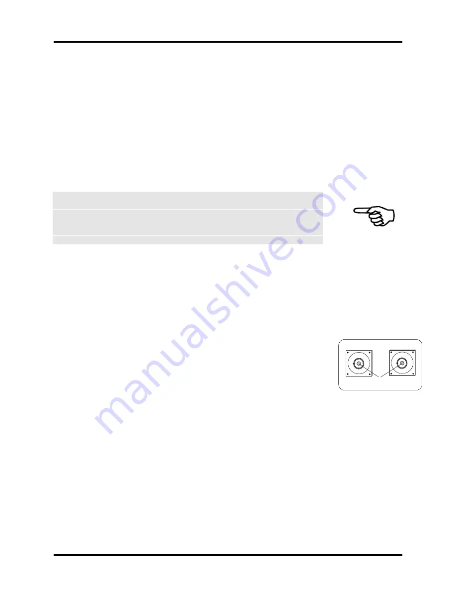
Rotate the motor shaft CW (as viewed looking into the motor shaft). The position
displayed should show a positive increase and stop counting when motor rotation stops.
The position may dither back and forth slightly, particularly on high-resolution systems,
even when the motor is at rest. If an axis is configured for dual feedback, be sure to verify
each feedback device.
2.9.3. Axis Loop Closure
Once establishing the proper feedback, the user should enable the drive to see if it can
hold position. The user can enable the drive by clicking on the axis name in the Manual
screen of the U600MMI. In AerDebug, deliver the command “SET DRIVE=1”. If
possible, turn the motor manually and let go, and the servo loop should return it to its
original position. The user should feel some shaft stiffness.
It is possible that moving the motor, or even enabling the drive causes instability. If so,
the axis needs tuning. See section 2.11.
Motor Mounting
Plate (Front View)
Motor Shaft
CW Rotation
CCW Rotation
(Positive Direction)
(Negative Direction)
Motor Mounting
Plate (Front View)
Summary of Contents for UNIDEX 600 Series
Page 19: ...Table of Contents U600 User s Guide xviii Aerotech Inc Version 1 4...
Page 27: ...Preface U600 User s Guide xxvi Aerotech Inc Version 1 4...
Page 163: ...AerPlot U600 User s Guide 6 6 Aerotech Inc Version 1 4...
Page 169: ...AerReg U600 User s Guide 8 4 Aerotech Inc Version 1 4...
Page 177: ...AerPlotIO U600 User s Guide 10 4 Aerotech Inc Version 1 4...
Page 179: ...Filter U600 User s Guide 11 2 Aerotech Inc Version 1 4...
Page 219: ...PrmSetup U600 User s Guide 13 2 Aerotech Inc Version 1 4...
Page 223: ...Glossary of Terms U600 User s Guide A 4 Aerotech Inc Version 1 4...
Page 353: ......


