


ENGINE
4-43
18. Install rocker and cam sprocket cover then torque bolts to
specification.
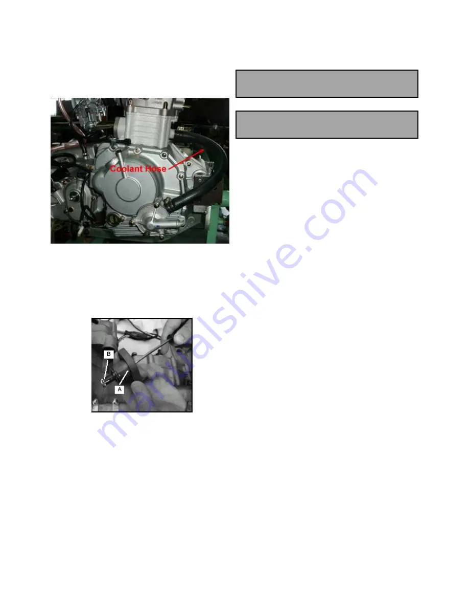
19. Connect coolant hose with cylinder and coolant pump.
CAM CHAIN TENSIONER INSTALLATION
1. Using a small flat blade screwdriver, turn the tensioner
clockwise to retract the plunger (B) all the way into the
tensioner body.
2. With the plunger retracted, install the tensioner assembly
with a new gasket and tighten the bolts to specification.
TENSIONER BOLT TORQUE:
10 Nm (7.4 ft. lbs.)
3. Install the tensioner cap. Torque cap to specification.
TENSIONER CAP TORQUE:
10 Nm (7.4 ft. lbs.)
4. Slowly rotate engine two to three revolutions and re-check
cam timing once chain is tight.
Summary of Contents for AT56-69E
Page 35: ...MAINTENANCE 2 25 ...
Page 45: ...CVT SYSTEM 3 4 CVT EXPLODED VIEW ...
Page 56: ...ENGINE 4 3 ENGINE ILLUSTRATION ENGINE EXPLODED VIEW ...
Page 57: ...ENGINE 4 4 ...
Page 58: ...ENGINE 4 5 COOLING SYSTEM EXPLODED VIEW ...
Page 59: ...ENGINE 4 6 OIL FLOW DIAGRAM ...
Page 125: ...FUEL AND CARBURETOR 6 15 FUEL TANK SYSTEM ...
Page 135: ...BODY SUSPENSION STEERING 7 6 SUSPENSION ...
Page 142: ...BODY SUSPENSION STEERING 7 13 STEERING ...
Page 151: ...BRAKES 8 6 FRONT BRAKE EXPLODED VIEW MASTER CYLINDER ...
Page 196: ...ELECTRICAL 9 31 WIRE DIAGRAM ...