


ENGINE
4-31
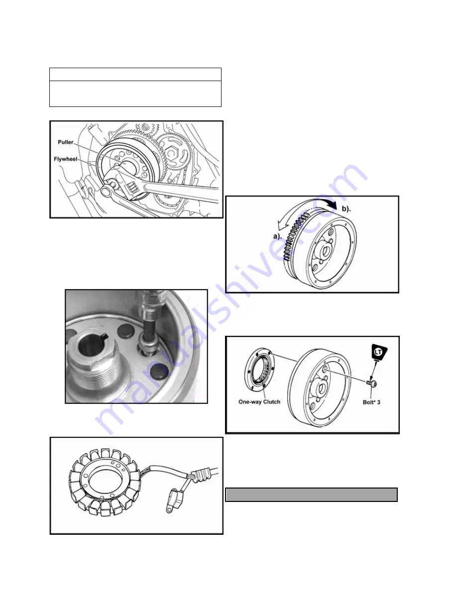
3. Remove flywheel.
CAUTION
Do not hammer or strike the tool while attached to
the crankshaft end, which may become damaged.
FLY WHEEL/ ONE-WAY CLUTCH
REMOVAL / INSPECTION
1. Remove the hex bolts that attach the one—way drive
clutch to the flywheel.
2. Check the stator and pickup. Replace it if has any
damaged.
3. Inspect the bearing surfaces and drive teeth for signs of
wear or gouging. Replace the one-way clutch as an assembly
if it is not working properly.
4. Install the starter wheel gear to the starter clutch, and hold
the starter clutch.
5. When turning the starter wheel gear counter clockwise a),
the starter clutch and the wheel gear should be engaged. If
not, the starter clutch is faulty. Replace it.
6. When turning the starter wheel gear clockwise b), the
starter wheel gear should turn freely. If not, the starter clutch
is faulty. Replace it.
6. To reattach the one-way assembly, apply Loctite 272 to
the retaining screw threads.
Torque to specification.
NOTE: One-Way clutch components are not
serviceable. Replace the component as an
assembly.
ONE-WAY CLUTCH SCREW TORQURE: 10 Nm
Summary of Contents for AT56-69E
Page 35: ...MAINTENANCE 2 25 ...
Page 45: ...CVT SYSTEM 3 4 CVT EXPLODED VIEW ...
Page 56: ...ENGINE 4 3 ENGINE ILLUSTRATION ENGINE EXPLODED VIEW ...
Page 57: ...ENGINE 4 4 ...
Page 58: ...ENGINE 4 5 COOLING SYSTEM EXPLODED VIEW ...
Page 59: ...ENGINE 4 6 OIL FLOW DIAGRAM ...
Page 125: ...FUEL AND CARBURETOR 6 15 FUEL TANK SYSTEM ...
Page 135: ...BODY SUSPENSION STEERING 7 6 SUSPENSION ...
Page 142: ...BODY SUSPENSION STEERING 7 13 STEERING ...
Page 151: ...BRAKES 8 6 FRONT BRAKE EXPLODED VIEW MASTER CYLINDER ...
Page 196: ...ELECTRICAL 9 31 WIRE DIAGRAM ...