


ENGINE
4-42
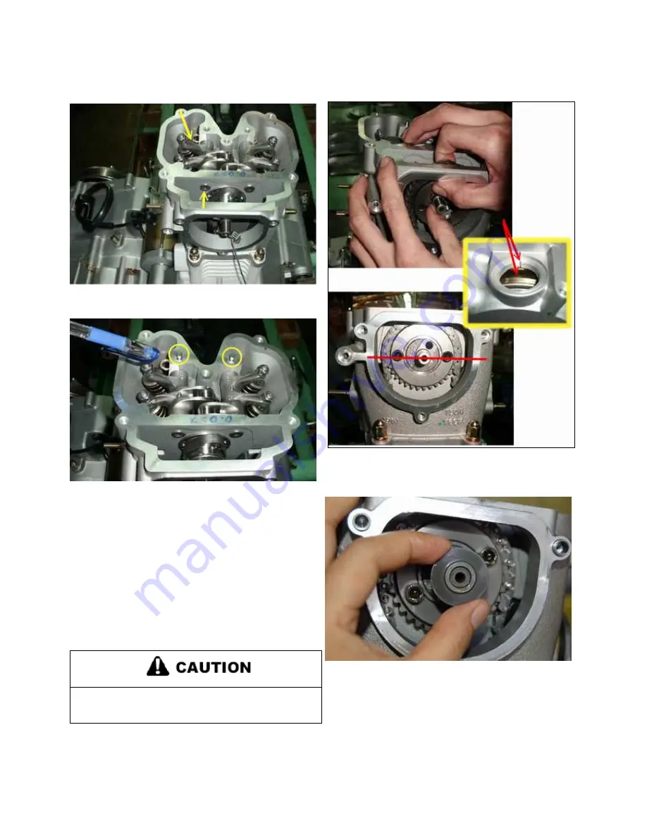
8. Install intake side rocker shaft and rocker arm.
9. Install 2 dowel pins onto cylinder head.
10. Ensure the piston locate At TDC (top die center).
11. Pull cam chain fully up then install cam sprocket into
camshaft.
12. Ensure cam sprockets 2 fasten holes, which locate at
horizontal.
13. Ensure flywheel mark align with right crank cover mark
line.
14. Tight cam sprocket fastens bolt.
Serious engine damage may result if the camshaft is
not properly timed to the crankshaft.
15. Install decompressor into camshaft.
16. Apply clean engine oil liberally to the valve springs, cam
chain, rocker arms, and camshaft.
17. Adjust valves according to the “VALVE
CLEARANCE ADJUSTMENT PROCEDURES”, Page4.39.
Summary of Contents for AT56-69E
Page 35: ...MAINTENANCE 2 25 ...
Page 45: ...CVT SYSTEM 3 4 CVT EXPLODED VIEW ...
Page 56: ...ENGINE 4 3 ENGINE ILLUSTRATION ENGINE EXPLODED VIEW ...
Page 57: ...ENGINE 4 4 ...
Page 58: ...ENGINE 4 5 COOLING SYSTEM EXPLODED VIEW ...
Page 59: ...ENGINE 4 6 OIL FLOW DIAGRAM ...
Page 125: ...FUEL AND CARBURETOR 6 15 FUEL TANK SYSTEM ...
Page 135: ...BODY SUSPENSION STEERING 7 6 SUSPENSION ...
Page 142: ...BODY SUSPENSION STEERING 7 13 STEERING ...
Page 151: ...BRAKES 8 6 FRONT BRAKE EXPLODED VIEW MASTER CYLINDER ...
Page 196: ...ELECTRICAL 9 31 WIRE DIAGRAM ...