


CVT SYSTEM
3-7
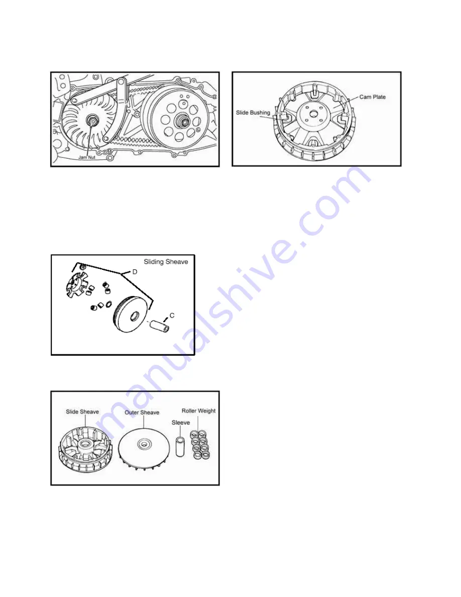
8. Remove outer sheave from crankshaft.
7. Remove belt.
8. Use two hands to hold the cam plate and the primary sliding
sheave together when removing the primary sliding sheave and
the cam plate assembly.
This prevents the roller weights from falling out of the
assembly.
5. Remove the roller weights from the primary sliding sheave.
Check the rollers for wear and scoring.
6. Remove and inspect the slide bushings and cam plate.
Replace any components that found to be worn excessively or
appear abnormal.
Summary of Contents for AT56-69E
Page 35: ...MAINTENANCE 2 25 ...
Page 45: ...CVT SYSTEM 3 4 CVT EXPLODED VIEW ...
Page 56: ...ENGINE 4 3 ENGINE ILLUSTRATION ENGINE EXPLODED VIEW ...
Page 57: ...ENGINE 4 4 ...
Page 58: ...ENGINE 4 5 COOLING SYSTEM EXPLODED VIEW ...
Page 59: ...ENGINE 4 6 OIL FLOW DIAGRAM ...
Page 125: ...FUEL AND CARBURETOR 6 15 FUEL TANK SYSTEM ...
Page 135: ...BODY SUSPENSION STEERING 7 6 SUSPENSION ...
Page 142: ...BODY SUSPENSION STEERING 7 13 STEERING ...
Page 151: ...BRAKES 8 6 FRONT BRAKE EXPLODED VIEW MASTER CYLINDER ...
Page 196: ...ELECTRICAL 9 31 WIRE DIAGRAM ...