


ENGINE
4-7
COOLING SYSTEM
SPECIFICATIONS
CONDITION
SPECIFICATION
Thermostat Open
65° C
Thermostat Full Open
80° C
System Capacity
1200CC
Fan Switch “On”
75° C/ 85° C (Two type)
Pressure Cap Relief
0.9 Bar
Recommended Coolant
Use only high quality antifreeze/coolant mixed with distilled
water in a 50/50 or 60/40 ratio, depending on freeze protection
required in your area.
PRESSURE TEST
1. Remove the front bumper.
2. Remove pressure cap and pressure test the cooling system
using a commercially available pressure tester.
3. The system must maintain 0.7 Bar (10 psi) for five minutes
or longer.
4. If pressure loss is evident within five minutes, check the
radiator, hose, lamps and water pump seals for leakage.
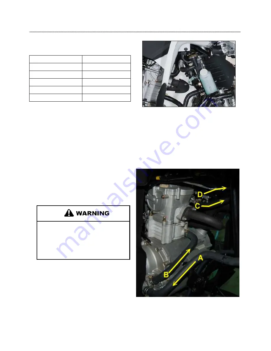
COOLANT CIRCULATION
A) From radiator to coolant pump.
B). From coolant pump to cylinder
C). From Thermostat valve to radiator
(High capacity circulation when coolant temperature over
65
℃
)
D). Bypass-from Thermostat bypass tube to radiator.
( low capacity circulation when coolant temperature below 65
℃
).
Pressure Cap Test
Never remove pressure cap when engine is
warm or hot. The cooling system is under
pressure and serious burns may result.
Allow the engine and cooling system to cool
before servicing.
1. Remove pressure cap and test cap using a commercially
available pressure cap tester.
2. The pressure cap relief pressure is 0.9 Bar (13 psi). Replace
cap if it does not meet this specification.
Summary of Contents for AT56-69E
Page 35: ...MAINTENANCE 2 25 ...
Page 45: ...CVT SYSTEM 3 4 CVT EXPLODED VIEW ...
Page 56: ...ENGINE 4 3 ENGINE ILLUSTRATION ENGINE EXPLODED VIEW ...
Page 57: ...ENGINE 4 4 ...
Page 58: ...ENGINE 4 5 COOLING SYSTEM EXPLODED VIEW ...
Page 59: ...ENGINE 4 6 OIL FLOW DIAGRAM ...
Page 125: ...FUEL AND CARBURETOR 6 15 FUEL TANK SYSTEM ...
Page 135: ...BODY SUSPENSION STEERING 7 6 SUSPENSION ...
Page 142: ...BODY SUSPENSION STEERING 7 13 STEERING ...
Page 151: ...BRAKES 8 6 FRONT BRAKE EXPLODED VIEW MASTER CYLINDER ...
Page 196: ...ELECTRICAL 9 31 WIRE DIAGRAM ...