


ENGINE
4-23
9. Lubricate the valve guides with clean engine oil, and apply
oil or water based lapping compound to the face of the valve.
Lapping is not required with an interference angle.
10. Insert the valve into its respective guide and lap using a
lapping tool or a section of fuel line connected to the valve
stem.
11. Rotate the valve rapidly back and forth until the cut sounds
smooth. Lift the valve slightly off of the seat, rotate 1/4 turn,
and repeat the lapping process. Do this four to five times until
the valve is fully seated, and repeat process for the other valve.
12. Clean cylinder head, valves, and camshaft oil supply
passages thoroughly.
13. Spray electrical contact cleaner into oil passages and dry
using compressed air.
CYLINDER HEAD ASSEMBLY
Wear eye protection during assembly.
NOTE: Assemble the valves one at a time to maintain
proper order.
1. Install new valve seals on valve guides.
2. Apply engine oil to valve guides and seats.
3. Coat valve stem with molybdenum disulfide grease.
4. Install valve carefully with a rotating motion to avoid
damaging valve seal.
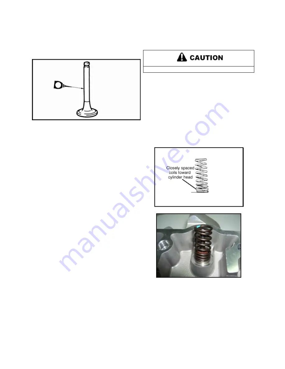
5. Dip valve spring and retainer in clean engine oil and install
spring with closely spaced coils toward the cylinder head.
Summary of Contents for AT56-69E
Page 35: ...MAINTENANCE 2 25 ...
Page 45: ...CVT SYSTEM 3 4 CVT EXPLODED VIEW ...
Page 56: ...ENGINE 4 3 ENGINE ILLUSTRATION ENGINE EXPLODED VIEW ...
Page 57: ...ENGINE 4 4 ...
Page 58: ...ENGINE 4 5 COOLING SYSTEM EXPLODED VIEW ...
Page 59: ...ENGINE 4 6 OIL FLOW DIAGRAM ...
Page 125: ...FUEL AND CARBURETOR 6 15 FUEL TANK SYSTEM ...
Page 135: ...BODY SUSPENSION STEERING 7 6 SUSPENSION ...
Page 142: ...BODY SUSPENSION STEERING 7 13 STEERING ...
Page 151: ...BRAKES 8 6 FRONT BRAKE EXPLODED VIEW MASTER CYLINDER ...
Page 196: ...ELECTRICAL 9 31 WIRE DIAGRAM ...