


CVT SYSTEM
3-6
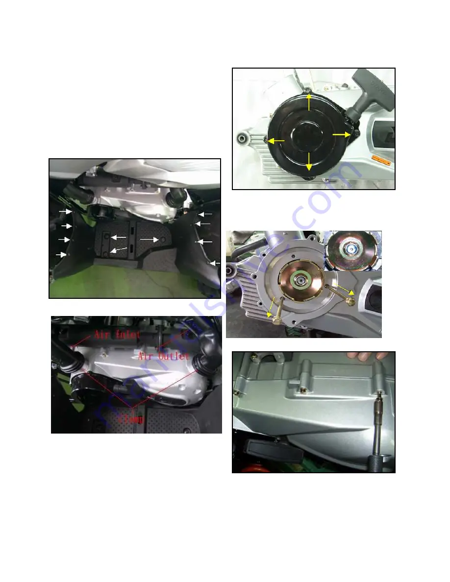
DRIVE CLUTCH REMOVAL
Some fasteners and procedures will vary. Refer to the
appropriate parts manual for proper fasteners and fastener
placement.
1. Position the vehicle on a level surface. Use the parking
brake.
2. Remove seat, storage box and LH plastic panel to gain
access to the outer clutch cover.
3. Remove the inlet dust screw and inlet duct.
4. Remove all screws and cover with re-coil start attached.
5. Remove the entire re-coil starter bolt.
6. Remove the lock nut, washer, and the re-coil start pawl from
the crankshaft.
7. Remove outer clutches cover screws and the clutch cover.
Summary of Contents for AT56-69E
Page 35: ...MAINTENANCE 2 25 ...
Page 45: ...CVT SYSTEM 3 4 CVT EXPLODED VIEW ...
Page 56: ...ENGINE 4 3 ENGINE ILLUSTRATION ENGINE EXPLODED VIEW ...
Page 57: ...ENGINE 4 4 ...
Page 58: ...ENGINE 4 5 COOLING SYSTEM EXPLODED VIEW ...
Page 59: ...ENGINE 4 6 OIL FLOW DIAGRAM ...
Page 125: ...FUEL AND CARBURETOR 6 15 FUEL TANK SYSTEM ...
Page 135: ...BODY SUSPENSION STEERING 7 6 SUSPENSION ...
Page 142: ...BODY SUSPENSION STEERING 7 13 STEERING ...
Page 151: ...BRAKES 8 6 FRONT BRAKE EXPLODED VIEW MASTER CYLINDER ...
Page 196: ...ELECTRICAL 9 31 WIRE DIAGRAM ...