


ENGINE
4-14
TOP END DISASSEMBLY
Oil Flow Test
Oil temperature can cause serious injury and
damage. Wear the proper safety gear when
performing these procedures.
NOTE: Due to the engine assembly having a majority
of roller bearings, oil pressure readings hot or cold
will be very low. Low oil pressure is not an indication
of an oil delivery problem.
1. Remove center plug from the stator housing on the
crankcase.
2. Insert an M6x8--1.00 oil pressure gauge adaptor into the
crankcase and attach a low pressure gauge (0--10psi /
0--70kpa).
3. Start engine and allow it to reach operating temperature
while monitoring gauge indicator.
Any pressure above zero is an indication of good oil flow.
CAM CHAIN TENSIONER REMOVAL
1. Remove oil fill cap from the stator housing and valve cover.
To position crankshaft at Top Dead Center (TDC) on
compression stroke:
2. Rotate engine slowly in the direction of rotation watching
intake valves open and start to close.
3. Continue to rotate engine slowly while watching camshaft
sprocket marks and the mark in the timing inspection hole.
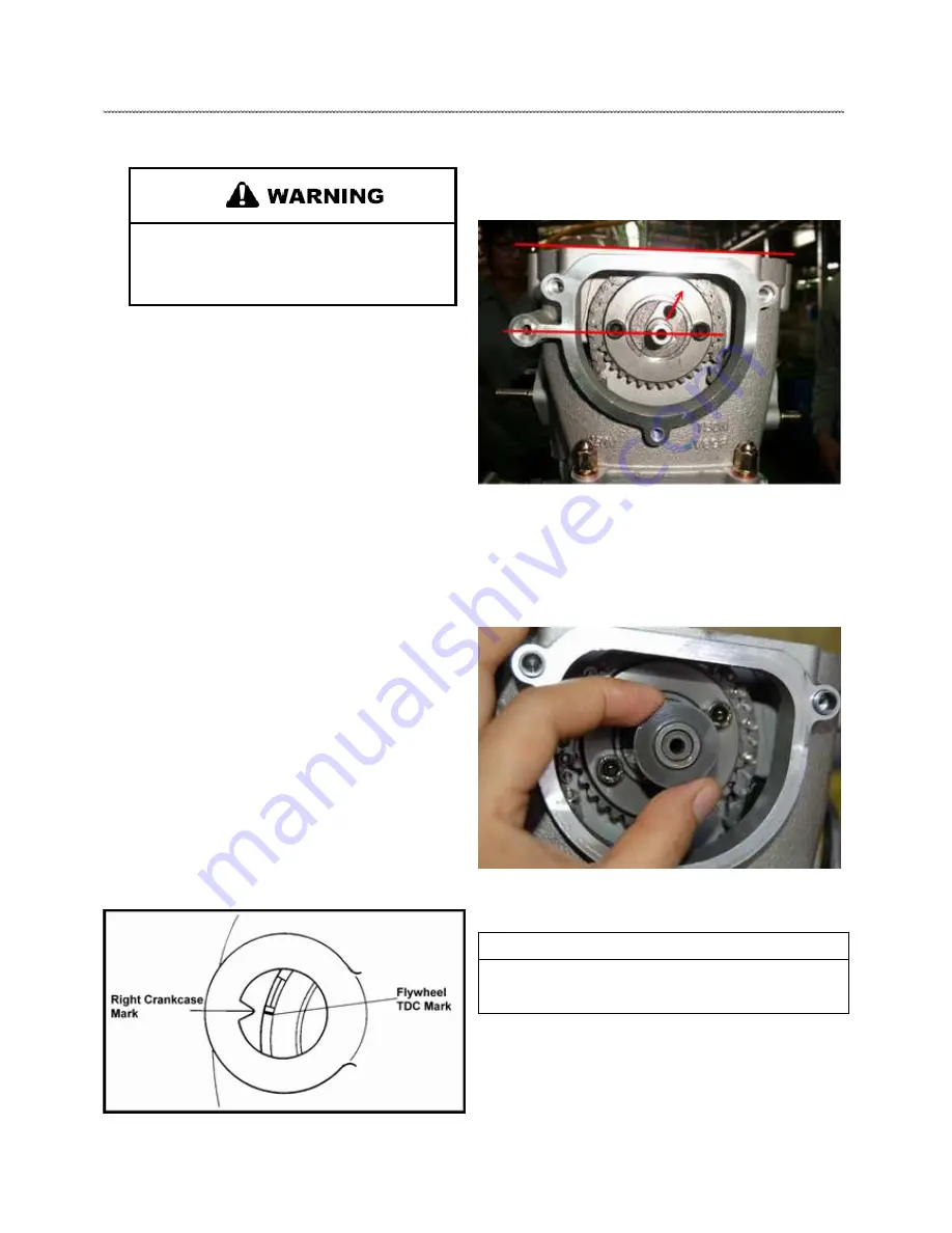
4. Align single (TDC) mark on flywheel with in the inspection
hole, and the cam sprocket holes (horizontal) aligned with the
gasket surface line.
NOTE: The sprocket marks align with gasket surface,
the cam lobes should be pointing down and the
valves should have clearance at this point.
5. Remove de-compressor from cam sprocket.
6. Remove the two cam chain tensioner flange bolts.
CAUTION
The plunger is under spring tension.
Maintain inward pressure while removing.
Summary of Contents for AT56-69E
Page 35: ...MAINTENANCE 2 25 ...
Page 45: ...CVT SYSTEM 3 4 CVT EXPLODED VIEW ...
Page 56: ...ENGINE 4 3 ENGINE ILLUSTRATION ENGINE EXPLODED VIEW ...
Page 57: ...ENGINE 4 4 ...
Page 58: ...ENGINE 4 5 COOLING SYSTEM EXPLODED VIEW ...
Page 59: ...ENGINE 4 6 OIL FLOW DIAGRAM ...
Page 125: ...FUEL AND CARBURETOR 6 15 FUEL TANK SYSTEM ...
Page 135: ...BODY SUSPENSION STEERING 7 6 SUSPENSION ...
Page 142: ...BODY SUSPENSION STEERING 7 13 STEERING ...
Page 151: ...BRAKES 8 6 FRONT BRAKE EXPLODED VIEW MASTER CYLINDER ...
Page 196: ...ELECTRICAL 9 31 WIRE DIAGRAM ...