


ENGINE
4-22
If the contact area of the cutter is in the same place, the valve
guide is distorted from improper installation and must be
replaced. Be sure the cylinder head is at the proper temperature
and replace the guide.
If the contact area of the initial cut is greater than 75%,
continue to cut the seat until all pits are removed and a new
seat surface is evident.
NOTE: Remove only the amount of material
necessary to repair the seat surface.
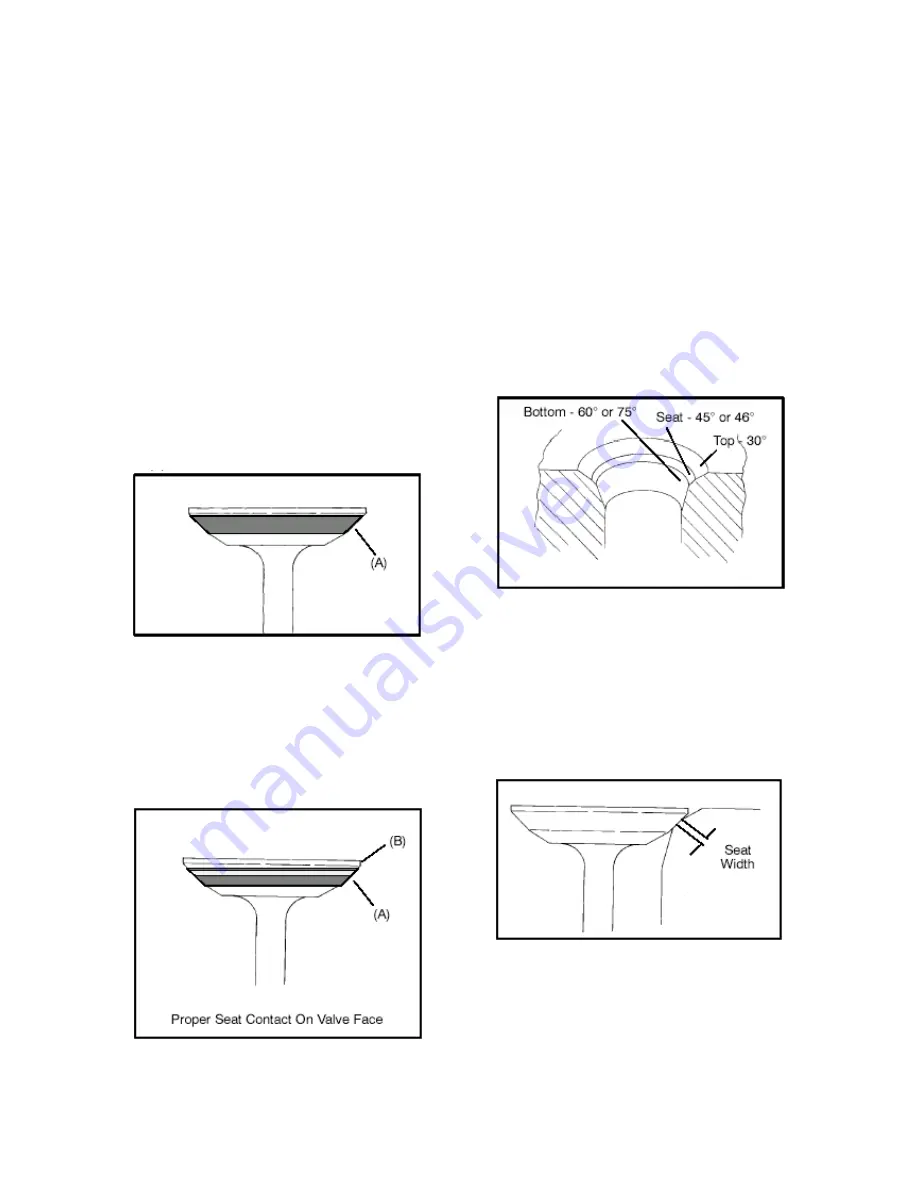
5. To check the contact area of the seat on the valve face, apply
a thin coating of Prussian Blue paste to the valve seat. If using
an interference angle (46
∘
) apply black marker to the entire
valve face (A).
6. Insert valve into guide and tap valve lightly into place a few
times.
7. Remove valve and check where the Prussian Blue or black
marker indicates seat contact on the valve face. The valve seat
should contact the middle of the valve face or slightly above,
and must be the proper width (A).
◎
If the indicated seat contact is at the top edge of the valve
face and contacts the margin area(B) it is too high on the valve
face. Use the 30
∘
cutter to lower the valve seat.
◎
If too low use the 60
∘
or 75
∘
cutter to raise the seat.
When contact area is centered on the valve face, measure seat
width.
◎
If the seat is too wide or uneven, use both top and bottom
cutters to narrow the seat.
◎
If the seat is too narrow, widen using the 45
∘
cutter and
re-check contact point on the valve face and seat width after
each cut.
NOTE: When using an interference angle, the seat
contact point on the valve will be very narrow, and is
a normal condition. Look for an even and continuous
contact point on the black marker, all the way around
the valve face.
8. Clean all filings from the area with hot soapy water, rinse,
and dry with compressed air.
Summary of Contents for AT56-69E
Page 35: ...MAINTENANCE 2 25 ...
Page 45: ...CVT SYSTEM 3 4 CVT EXPLODED VIEW ...
Page 56: ...ENGINE 4 3 ENGINE ILLUSTRATION ENGINE EXPLODED VIEW ...
Page 57: ...ENGINE 4 4 ...
Page 58: ...ENGINE 4 5 COOLING SYSTEM EXPLODED VIEW ...
Page 59: ...ENGINE 4 6 OIL FLOW DIAGRAM ...
Page 125: ...FUEL AND CARBURETOR 6 15 FUEL TANK SYSTEM ...
Page 135: ...BODY SUSPENSION STEERING 7 6 SUSPENSION ...
Page 142: ...BODY SUSPENSION STEERING 7 13 STEERING ...
Page 151: ...BRAKES 8 6 FRONT BRAKE EXPLODED VIEW MASTER CYLINDER ...
Page 196: ...ELECTRICAL 9 31 WIRE DIAGRAM ...