


MAINTENANCE
2-7
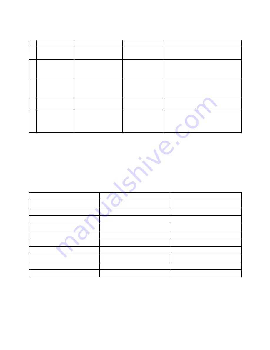
MAINTENANCE QUICK REFERENCE
Item
Comment
Method
Frequency
1
Engine Oil
OW-50 Synthetic
20W-40 Semi-Synthetic
Check level or
change oil
Check during pre-ride inspection change
oil every 30 hours or 6 months.
2
Transmission
SAE80W-90 Gear
Lubricant
Check level or
change lube.
Inspect periodically and change
lubrication every 40 hours or annually.
More often in severe use.
3
Brake Fluid
DOT-4 Brake Fluid
Fill master cylinder
reservoir to indicated
lever inside reservoir.
As require. Change fluid every 2 years.
4
Radiator Coolant
50% Glycol with 50%
Water
Fill Ext. tank to
indicated lever.
Check Exe. Tank lever pre-ride.
Change coolant yearly.
5
Front Suspension
A-Arm and Spindle)
Premium All Season
Grease
Inspect; tighten
fasteners; grease
zerks
Every 3 months or 50 hours (also after
washing SxS or driving in water). More
often in severe use.
Frame, Nuts, Bolts and Fastener Inspection
Periodically inspect the torque of all fasteners in accordance with the maintenance schedule. Check that all cotter pins are in
place. Refer to specific fastener torques listed in each chapter.
STANDARD TORQUE SPECIFICATIONS
The following torque specifications are to be used as a general guideline. There are exceptions in the steering, suspension, and
engine areas. Always consult the exploded views in each manual section when available for torque values of fasteners before
using standard torque.
Standard Fastener Torques
Thread Size
Torque (ft. lbs. / in. lbs.)
Torque (Nm)
5 mm bolts and nuts
39-52 in. lbs.
4.5-6 Nm
6 mm bolt and nuts
69-104 in. lbs.
8-12 Nm
8 mm bolts and nuts
13-18 ft. lbs.
18-25 Nm
10 mm bolts and nuts
22-29 ft. lbs.
30-40 Nm
12 mm bolts and nuts
36-43 ft. lbs.
50-60 Nm
4 mm screws
22-30 in. lbs.
2.5-3.4 Nm
5 mm screws
30-43 in. lbs.
3.5-5 Nm
6 mm Hex bolts
87-121 in. lbs.
10-14 Nm
8 mm Hex bolts
17-22 ft. lbs.
24-30 Nm
10 mm Hex bolts
25-32 ft. lbs.
35-45 Nm
Summary of Contents for AT56-69E
Page 35: ...MAINTENANCE 2 25 ...
Page 45: ...CVT SYSTEM 3 4 CVT EXPLODED VIEW ...
Page 56: ...ENGINE 4 3 ENGINE ILLUSTRATION ENGINE EXPLODED VIEW ...
Page 57: ...ENGINE 4 4 ...
Page 58: ...ENGINE 4 5 COOLING SYSTEM EXPLODED VIEW ...
Page 59: ...ENGINE 4 6 OIL FLOW DIAGRAM ...
Page 125: ...FUEL AND CARBURETOR 6 15 FUEL TANK SYSTEM ...
Page 135: ...BODY SUSPENSION STEERING 7 6 SUSPENSION ...
Page 142: ...BODY SUSPENSION STEERING 7 13 STEERING ...
Page 151: ...BRAKES 8 6 FRONT BRAKE EXPLODED VIEW MASTER CYLINDER ...
Page 196: ...ELECTRICAL 9 31 WIRE DIAGRAM ...