


MAINTENANCE
2-8
RE-COIL OIL STARTER AND OPERATION
If the battery becomes too weak to start the engine, use the
re-coil starter to start the engine until the battery is serviced.
1. Position the vehicle on a level surface.
2. Shift the transmission into neutral (if equipped).
3. Lock the parking brake.
4. Push the engine stop switch up to the RUN position.
5. Turn the key ON.
6. Pull the re-coil to crank the engine.
THROTTLE INSPECTION
If the throttle has excessive play due to cable stretch or cable
maladjustment, it will cause a delay in throttle speed. Also, the
throttle may not open fully. If the throttle lever has no play, the
throttle may be hard to control, and the idle speed may be erratic.
Check the throttle free play periodically in accordance with the
Periodic Maintenance Chart and adjust the play if necessary.
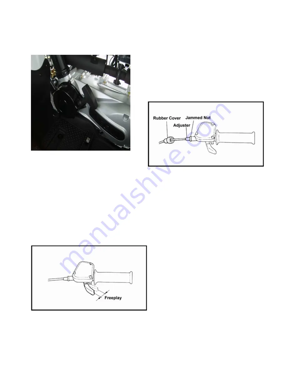
Throttle Free Play Adjustment
Inspection
1. Place the transmission in the N position.
2. Start the engine, and warm it up thoroughly.
3. Measure the distance the throttle lever moves before the
engine begins to pick up speed. Free play should be 1.5 - 3 mm
(1/16” - 1/8”).
Adjustment
1. Squeeze the end of the rubber boot and slide it far enough to
expose the end of the inline cable adjuster.
2. Loosen the adjuster lock nut.
3. Rotate the boot to turn the adjuster until 1.5 - 3 mm (1/16" to
1/8") of free play is achieved at the throttle pedal.
NOTE: While adjusting, lightly flip the throttle pedal up
and down.
4. Tighten the lock nut.
5. Squeeze the end of the rubber boot and slide it over the cable
adjuster to its original position.
Adjusting The Speed Limiter
The speed limiter keeps the carburetor throttle from becoming
fully opened even when the throttle lever is applied to the
maximum position.
Screwing in the adjuster stops the engine speed from increasing.
Summary of Contents for AT56-69E
Page 35: ...MAINTENANCE 2 25 ...
Page 45: ...CVT SYSTEM 3 4 CVT EXPLODED VIEW ...
Page 56: ...ENGINE 4 3 ENGINE ILLUSTRATION ENGINE EXPLODED VIEW ...
Page 57: ...ENGINE 4 4 ...
Page 58: ...ENGINE 4 5 COOLING SYSTEM EXPLODED VIEW ...
Page 59: ...ENGINE 4 6 OIL FLOW DIAGRAM ...
Page 125: ...FUEL AND CARBURETOR 6 15 FUEL TANK SYSTEM ...
Page 135: ...BODY SUSPENSION STEERING 7 6 SUSPENSION ...
Page 142: ...BODY SUSPENSION STEERING 7 13 STEERING ...
Page 151: ...BRAKES 8 6 FRONT BRAKE EXPLODED VIEW MASTER CYLINDER ...
Page 196: ...ELECTRICAL 9 31 WIRE DIAGRAM ...