


CVT SYSTEM
3-9
DRIVEN CLUTCH SERVICE
DRIVEN CLUTCH DISASSEMBLY AND
INSPECTION
1. Inspect the condition of the clutch drum. Measure the inside
diameter of the cover at 90 degree intervals using a caliper.
Inspect the condition and diameter of the drum lining. If either
the measurements or the lining indicates excessive wear,
replace the clutch cover.
Spring pressure can cause components to eject
suddenly. Use care during removal.
1. Secure the assembly in a clamping device. To access the
driven spring, mark and remove the outer heave-retaining nut.
Remove the friction pad assembly and driven spring.
2. Inspect the condition of the clutch drum. Measure the inside
diameter of the cover at 90 degree intervals using a caliper.
Inspect the condition and diameter of the drum lining. If either
the measurements or the lining indicates excessive wear,
replace the clutch cover.
Driven Clutch Friction Pad
Service Limit: 2 mm (0.078”)
Driven Clutch Hub I. D.:
Service Limit: 153
﹢
0.2 mm
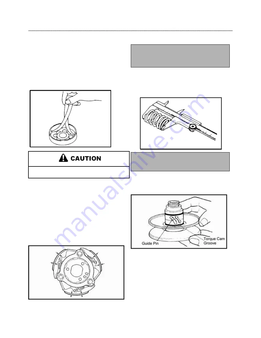
3. Use a caliper to check the length of the compression
spring. At full extension, the measurement should be no less
than 130 mm. If out of specification, replace the spring.
Driven Compression Spring
Service Limit:
130 mm (51.2”)
4. Remove the outer guide pin cover by turning and pulling
up on the cover. Replace the 2 o--rings.
5. Remove the rollers and pins using a needle—nose pliers
and inspect all components. Replace if any damage or excess
wear is found. Replace the o--rings and seals anytime the
driven is apart.
Summary of Contents for AT56-69E
Page 35: ...MAINTENANCE 2 25 ...
Page 45: ...CVT SYSTEM 3 4 CVT EXPLODED VIEW ...
Page 56: ...ENGINE 4 3 ENGINE ILLUSTRATION ENGINE EXPLODED VIEW ...
Page 57: ...ENGINE 4 4 ...
Page 58: ...ENGINE 4 5 COOLING SYSTEM EXPLODED VIEW ...
Page 59: ...ENGINE 4 6 OIL FLOW DIAGRAM ...
Page 125: ...FUEL AND CARBURETOR 6 15 FUEL TANK SYSTEM ...
Page 135: ...BODY SUSPENSION STEERING 7 6 SUSPENSION ...
Page 142: ...BODY SUSPENSION STEERING 7 13 STEERING ...
Page 151: ...BRAKES 8 6 FRONT BRAKE EXPLODED VIEW MASTER CYLINDER ...
Page 196: ...ELECTRICAL 9 31 WIRE DIAGRAM ...