


MAINTENANCE
2-19
ELECTRICAL AND IGNITION SYSTEM
2. Slowly remove the pressure cap to relieve any cooling
system pressure.
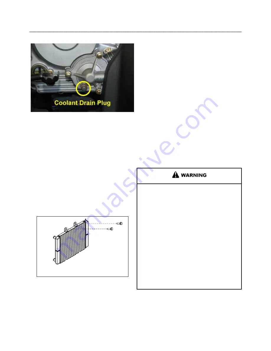
3. Place a suitable drain pan underneath the water pump on the
RH side of the engine.
4. Drain the coolant from the water pump radiator.
5. Allow coolant to completely drain.
Radiator Removal
1. Remove the front bumper.
2. Remove the upper engine outlet hose and recovery hose
from the top of the radiator.
3. Remove the (2) upper radiator retaining bolts and the
Remove the bracket from the frame.
4. Disconnect the fan motor and remove the radiator from the
vehicle. Take care not to damage the cooling fins.
5. Reverse procedure for installation.
BATTERY MAINTENANCE
Keep battery terminals and connections free of corrosion. If
cleaning is necessary, remove the corrosion with a stiff wire
brush. Wash with a solution of one-tablespoon baking soda
and one cup water. Rinse well with tap water and dry off with
clean shop towels. Coat the terminals with dielectric grease or
petroleum jelly.
Be careful not to allow cleaning solution or tap water into the
battery.
NOTE: Batteries must be fully charged before use or
battery life will be reduced by 10-30% of full potential.
Charge battery for 3-5 hours at a current equivalent
of 1/10 of the battery rated amp/hour capacity. Do not
use the alternator to charge a new battery.
Battery Removal
Battery electrolyte is poisonous. It contains sulfuric
acid. Serious burns can result from contact with
skin, eyes or clothing. Antidote:
External: Flush with water.
Internal: Drink large quantities of water or milk.
Follow with milk of magnesia, beaten egg, or
vegetable oil. Call physician immediately.
Eyes: Flush with water for 15 minutes and get
prompt medical attention.
Batteries produce explosive gases. Keep sparks,
flame, cigarettes, etc. away. Ventilate when charging
or using in an enclosed space. Always shield eyes
when working near batteries.
KEEP OUT OF REACH OF CHILDREN.
Summary of Contents for AT56-69E
Page 35: ...MAINTENANCE 2 25 ...
Page 45: ...CVT SYSTEM 3 4 CVT EXPLODED VIEW ...
Page 56: ...ENGINE 4 3 ENGINE ILLUSTRATION ENGINE EXPLODED VIEW ...
Page 57: ...ENGINE 4 4 ...
Page 58: ...ENGINE 4 5 COOLING SYSTEM EXPLODED VIEW ...
Page 59: ...ENGINE 4 6 OIL FLOW DIAGRAM ...
Page 125: ...FUEL AND CARBURETOR 6 15 FUEL TANK SYSTEM ...
Page 135: ...BODY SUSPENSION STEERING 7 6 SUSPENSION ...
Page 142: ...BODY SUSPENSION STEERING 7 13 STEERING ...
Page 151: ...BRAKES 8 6 FRONT BRAKE EXPLODED VIEW MASTER CYLINDER ...
Page 196: ...ELECTRICAL 9 31 WIRE DIAGRAM ...