199
Apparatus control
&KDSWHU
&RQWURO
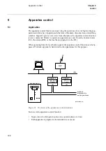
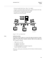
Figure 85 shows the information exchange connections for one bay with up to 14 appa-
ratuses.
)LJXUH &RQQHFWLRQVEHWZHHQWZR%$<&21VLQWHQGHGWRFRQWUROXSWRDSSDUD
WXVHV
6HOHFWLRQUHOD\VXSHUYLVLRQ
The normal use of the command output module (BOM) does not require any external
relays. The supervision of the command relays on the output module is performed on
the circuit board. The output module is normally connected directly to the switchyard
without any extra relays.
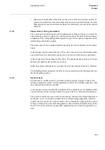
To meet requirements of supervision of external selection relays, it is possible to con-
nect these relays and supervise them by BAYCONE or BAYCONF with individual
feedback signals shown in figure 86.
The auxiliary contacts of the relays are wired to two inputs SEL_CH1 and SEL_CH2.
A series connection of NC contacts connected to SEL_CH1 indicates that no relay is
energized. A parallel connection of NO contacts connected to SEL_CH2 indicates that
a relay is energized. BAYCON can now determine two types of errors. It can indicate
that there is an error most probably at the system inputs with the BINPERR. BOUTERR
indicates that the error is more likely to be found at the system outputs. BAYCON also
checks the selection relays separately with a feedback signal from the energized selec-
tion relay. It can then determine if wrong relay is energized. It indicates this with the
BRLYERR output. When an error occurs, BAYCON cancels all operations. It lets the
reservation go into a fail state, which causes resetting of the selection or acknowledge-
ment.
When BAYCON has a valid reservation for a selection request and no error occurs, the
selection relay supervision also sets an output to the requesting apparatus. This is a
feedback selection (FDB_SELx), which indicates that the energizing of the relay was
correct. Now other software parts can give a close or open command.
en02000571.vsd
EXCH_OUT
EXCH_IN
BAYCON
EXCH_IN
BAYCON
EXCH_OUT
Summary of Contents for REO 517
Page 10: ... RQWHQWV ...
Page 16: ...6 Introduction to the application manual KDSWHU QWURGXFWLRQ ...
Page 64: ...54 Blocking of signals during test KDSWHU RPPRQ IXQFWLRQV ...
Page 88: ...78 Scheme communication logic ZCOM KDSWHU LQH LPSHGDQFH ...
Page 146: ...136 Unbalance protection for capacitor banks TOCC KDSWHU XUUHQW ...
Page 166: ...156 Dead line detection DLD KDSWHU 3RZHU V VWHP VXSHUYLVLRQ ...
Page 378: ...368 Monitoring of DC analog measurements KDSWHU 0RQLWRULQJ ...
Page 384: ...374 Pulse counter logic PC KDSWHU 0HWHULQJ ...
Page 412: ...402 Serial communication modules SCM KDSWHU DWD FRPPXQLFDWLRQ ...
Page 440: ...430 LED indication module KDSWHU DUGZDUH PRGXOHV ...


