


35
Logic function blocks
&KDSWHU
&RPPRQIXQFWLRQV
25
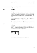
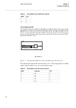
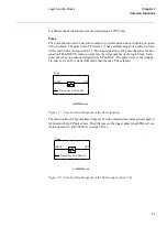
OR function blocks are used to form general combinatory expressions with boolean
variables. The function block (figure 8) has six inputs, designated Onnn-INPUTm,
where nnn presents the serial number of the block, and m presents the serial number of
the inputs in the block. Each OR circuit has two outputs, Onnn-OUT and Onnn-NOUT
(inverted).
)LJXUH )XQFWLRQEORFNGLDJUDPRIWKH25IXQFWLRQ
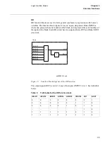
The output signal (OUT) is set to 1 if any of the inputs (INPUT1-6) is 1. See truth table
below.
7DEOH
7UXWKWDEOHIRUWKH25IXQFWLRQEORFN
≥
1
INPUT6
INPUT1
INPUT2
INPUT3
INPUT4
INPUT5
OUT
1
NOUT
Onnn
xx00000514.vsd
,1387
,1387
,1387
,1387
,1387
,1387
287
1287
0
0
0
0
0
0
0
1
0
0
0
0
0
1
1
0
0
0
0
0
1
0
1
0
...
...
...
...
...
...
1
0
1
1
1
1
1
0
1
0
1
1
1
1
1
1
1
0
Summary of Contents for REO 517
Page 10: ... RQWHQWV ...
Page 16: ...6 Introduction to the application manual KDSWHU QWURGXFWLRQ ...
Page 64: ...54 Blocking of signals during test KDSWHU RPPRQ IXQFWLRQV ...
Page 88: ...78 Scheme communication logic ZCOM KDSWHU LQH LPSHGDQFH ...
Page 146: ...136 Unbalance protection for capacitor banks TOCC KDSWHU XUUHQW ...
Page 166: ...156 Dead line detection DLD KDSWHU 3RZHU V VWHP VXSHUYLVLRQ ...
Page 378: ...368 Monitoring of DC analog measurements KDSWHU 0RQLWRULQJ ...
Page 384: ...374 Pulse counter logic PC KDSWHU 0HWHULQJ ...
Page 412: ...402 Serial communication modules SCM KDSWHU DWD FRPPXQLFDWLRQ ...
Page 440: ...430 LED indication module KDSWHU DUGZDUH PRGXOHV ...