


177
Automatic reclosing function (AR)
&KDSWHU
&RQWURO
$XWRPDWLFFRQILUPDWLRQRISURJUDPPHGUHFORVLQJDWWHPSWV
The auto-recloser can be programmed to continue with reclosing attempts two to four
(if selected) even if the start signals are not received from the protection functions, but
the breaker is still not closed. See figure in Function block diagrams. This is done by
setting the parameter
$XWR&RQW
= On and the wait time
W$XWR:DLW
to desired length.
&DOFXODWLRQV
&RQILJXUDWLRQDQGVHWWLQJ
The signals are configured in the CAP configuration tool.
The parameters for the automatic reclosing function are set via the local HMI or PST
(Parameter Setting Tool). Refer to the Technical reference manual for setting parame-
ters and path in local HMI.
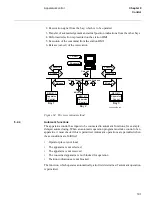
5HFRPPHQGDWLRQVIRULQSXWVLJQDOV
See figure 77 "Recommendations for I/O-signal connections" on page 179 and the de-
fault configuration for examples.
$567$57
Should be connected to the protection function trip output which shall start the auto-re-
closer. It can also be connected to a binary input for start from an external contact. A
logical OR gate can be used to multiply the number of start sources.
$521DQG$52))
May be connected to binary inputs for external control.
$5,1+,%,7
Can be connected to binary inputs, to block the AR from a certain protection, such as a
line connected shunt reactor, transfer trip receive or back-up protection or breaker-fail-
ure protection.
$5&%&/26('DQG$5&%5($'<
Must be connected to binary inputs, for pick-up of the breaker signals. If the external
signals are of Breaker-not-ready type, uncharged etc., an inverter can be configured be-
fore CBREADY.
$56<1&
Is connected to the internal synchro-check function if required. It can also be connected
to a binary input. If neither internal nor external synchronizing or energizing check
(dead line check) is required, it can be connected to a permanent 1 (high), by connection
to FIXD-ON.
Summary of Contents for REO 517
Page 10: ... RQWHQWV ...
Page 16: ...6 Introduction to the application manual KDSWHU QWURGXFWLRQ ...
Page 64: ...54 Blocking of signals during test KDSWHU RPPRQ IXQFWLRQV ...
Page 88: ...78 Scheme communication logic ZCOM KDSWHU LQH LPSHGDQFH ...
Page 146: ...136 Unbalance protection for capacitor banks TOCC KDSWHU XUUHQW ...
Page 166: ...156 Dead line detection DLD KDSWHU 3RZHU V VWHP VXSHUYLVLRQ ...
Page 378: ...368 Monitoring of DC analog measurements KDSWHU 0RQLWRULQJ ...
Page 384: ...374 Pulse counter logic PC KDSWHU 0HWHULQJ ...
Page 412: ...402 Serial communication modules SCM KDSWHU DWD FRPPXQLFDWLRQ ...
Page 440: ...430 LED indication module KDSWHU DUGZDUH PRGXOHV ...