


255
Interlocking
&KDSWHU
&RQWURO
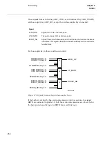
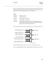
•
Q75_OP = 1
•
Q75_CL = 0
•
BC_AB_CL = 0
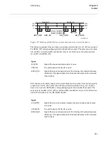
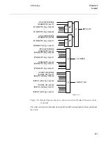
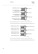
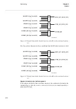
If there is no second busbar B and therefore no Q20 and Q2 disconnectors, then the in-
terlocking for Q20 and Q2 are not used. The states for Q20, Q2, Q25, BC_AB, BBTR
are set to open by setting the appropriate module inputs as follows. In the functional
block diagram, 0 and 1 are designated 0=FIXD-OFF and 1=FIXD-ON:
•
Q20_OP = 1
•
Q20_CL = 0
•
Q2_OP = 1
•
Q2_CL = 0
•
Q25_OP = 1
•
Q25_CL = 0
•
BC_AB_CL = 0
•
BBTR_OP = 1
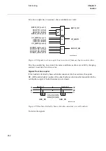
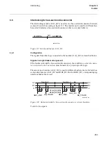
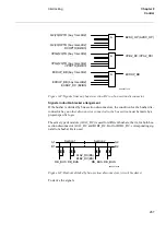
,QWHUORFNLQJIRUWUDQVIRUPHUED\
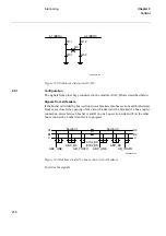
The interlocking module AB_TRAFO is used for a transformer bay connected to a dou-
ble busbar arrangement according to figure 131. The module is used when there is no
disconnector between circuit breaker and transformer. Otherwise, the module
ABC_LINE can be used. This module can also be used for a single busbar arrangement.
Summary of Contents for REO 517
Page 10: ... RQWHQWV ...
Page 16: ...6 Introduction to the application manual KDSWHU QWURGXFWLRQ ...
Page 64: ...54 Blocking of signals during test KDSWHU RPPRQ IXQFWLRQV ...
Page 88: ...78 Scheme communication logic ZCOM KDSWHU LQH LPSHGDQFH ...
Page 146: ...136 Unbalance protection for capacitor banks TOCC KDSWHU XUUHQW ...
Page 166: ...156 Dead line detection DLD KDSWHU 3RZHU V VWHP VXSHUYLVLRQ ...
Page 378: ...368 Monitoring of DC analog measurements KDSWHU 0RQLWRULQJ ...
Page 384: ...374 Pulse counter logic PC KDSWHU 0HWHULQJ ...
Page 412: ...402 Serial communication modules SCM KDSWHU DWD FRPPXQLFDWLRQ ...
Page 440: ...430 LED indication module KDSWHU DUGZDUH PRGXOHV ...