


154
Dead line detection (DLD)
&KDSWHU
3RZHUV\VWHPVXSHUYLVLRQ
'HDGOLQHGHWHFWLRQ'/'
$SSOLFDWLRQ
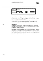
The function for detecting dead lines, DLD is intended for single- and two-phase sys-
tems. The function establishes whether the protected line is energized or not.
The output signal from the DLD-function is used as an input signal in other fault pro-
tection functions (for example SOTF). Accordingly, the output signal from the DLD-
function should always be configured to the corresponding input logical fault protection
function.
)XQFWLRQDOLW\
The DLD-function uses the standard undervoltage function TUV to monitor the voltage
on the line. The voltage input UL1 is used to supervise single-phase systems while UL1
and UL2 are used in two-phase systems. This means that the DLD-function does not
have its own voltage settings.
The minimum current level in the impedance function is used to supervise the currents.
For voltage supervision the normal undervoltage function, TUV, is used. Consequently,
the DLD-function does not feature its own settings.
The measured current and voltage values are compared to the set operate values IMinop
and UPE<. The logical signals STMILn have the value logical 1 if the current in the cor-
responding phase is less than the set operate value IMinop. The logical signals STULnN
have the value logical 1 if the voltage in the corresponding phase is less than the set op-
erate value UPE<.
The output signal DLD-START is activated without delay when all the currents and
voltages are under the set operate value. The signal resets with a delay of 15 ms, when
a voltage or current exceeds the set operate value.
Summary of Contents for REO 517
Page 10: ... RQWHQWV ...
Page 16: ...6 Introduction to the application manual KDSWHU QWURGXFWLRQ ...
Page 64: ...54 Blocking of signals during test KDSWHU RPPRQ IXQFWLRQV ...
Page 88: ...78 Scheme communication logic ZCOM KDSWHU LQH LPSHGDQFH ...
Page 146: ...136 Unbalance protection for capacitor banks TOCC KDSWHU XUUHQW ...
Page 166: ...156 Dead line detection DLD KDSWHU 3RZHU V VWHP VXSHUYLVLRQ ...
Page 378: ...368 Monitoring of DC analog measurements KDSWHU 0RQLWRULQJ ...
Page 384: ...374 Pulse counter logic PC KDSWHU 0HWHULQJ ...
Page 412: ...402 Serial communication modules SCM KDSWHU DWD FRPPXQLFDWLRQ ...
Page 440: ...430 LED indication module KDSWHU DUGZDUH PRGXOHV ...