148
Line test function (LITE)
&KDSWHU
9ROWDJH
/LQHWHVWIXQFWLRQ/,7(
$SSOLFDWLRQ
The line testing function, LITE is intended for single-phase systems where a test break-
er is installed in parallel with the regular circuit breaker. The test breaker is equipped
with a series resistor/inductor and is used during switching operations to reduce the risk
of closing the regular breaker against a persistent fault.
The line testing function is part of a test function that determines whether the line is
clear of faults before the line-breaker receives the closing pulse. This should occur with
manual closing and breaker closing from automatic reclosing (AR) control equipment.
In addition to the line testing function, the reclosing control system for the line breaker
principally consists of the auto-recloser function, paralleling/energizing function, test
breaker, line breaker and measuring unit.
Two different operating methods can be chosen.
•
Closing of the line-breaker is permitted if the test-breaker is connected and the line
voltage, when energized via the test-breaker, is higher then the set minimum line
voltage.
•
Closing of the line-breaker is permitted if both the line and busbar voltage is higher
then the minimum voltage or if the line is energized via the test-breaker and the line
voltage is higher than the set minimum line voltage.
An integrated test function can be activated to check operation of the line test equip-
ment. The line-breaker truck must be withdrawn and closed to test the line test equip-
ment. A start signal is given to the line test function and a line fault simulated by
applying an open signal. This gives an opening pulse to the line-breaker and a start pulse
to the reclosing function. The line-breaker can then be reconnected by means of a start
signal to the line testing function.
)XQFWLRQDOLW\
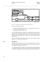
The measuring element in one of the built-in signal processors continuously measures
the line and busbar voltages. They are processed in elliptical filters before the funda-
mental frequency RMS values are calculated. A separate trip counter prevents over-
reach or underreach of the measuring element. When the measured voltage exceeds the
set operate value, the measuring element's output signal is activated.
Summary of Contents for REO 517
Page 10: ... RQWHQWV ...
Page 16: ...6 Introduction to the application manual KDSWHU QWURGXFWLRQ ...
Page 64: ...54 Blocking of signals during test KDSWHU RPPRQ IXQFWLRQV ...
Page 88: ...78 Scheme communication logic ZCOM KDSWHU LQH LPSHGDQFH ...
Page 146: ...136 Unbalance protection for capacitor banks TOCC KDSWHU XUUHQW ...
Page 166: ...156 Dead line detection DLD KDSWHU 3RZHU V VWHP VXSHUYLVLRQ ...
Page 378: ...368 Monitoring of DC analog measurements KDSWHU 0RQLWRULQJ ...
Page 384: ...374 Pulse counter logic PC KDSWHU 0HWHULQJ ...
Page 412: ...402 Serial communication modules SCM KDSWHU DWD FRPPXQLFDWLRQ ...
Page 440: ...430 LED indication module KDSWHU DUGZDUH PRGXOHV ...

