


259
Interlocking
&KDSWHU
&RQWURO
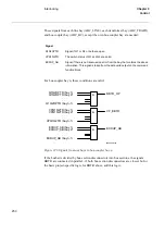
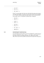
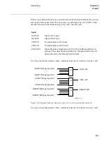
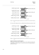
These signals from each line bay (ABC_LINE), each transformer bay (ABC_TRAFO),
and bus-coupler bay (ABC_BC) are needed:
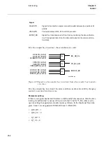
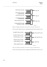
These signals from each bus-coupler bay (ABC_BC) are needed:
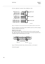
These signals from the bus-section circuit breaker bay (A1A2_BS, B1B2_BS) are need-
ed.
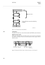
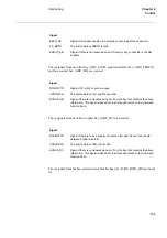
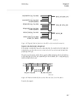
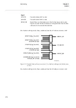
6LJQDO
BBTR_OP
Signal if no busbar transfer is in progress concerning this bus section.
VP_BBTR
The switch status of BBTR is valid.
EXDUP_AB
Signal if there is no transmission error from any bay connected to the AB
busbars.
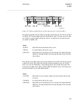
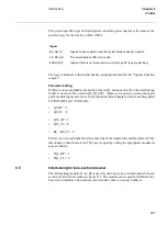
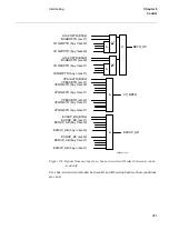
6LJQDO
Q1Q2OPTR
Signal if Q1 or Q2 or both are open.
VPQ1Q2TR
The switch status of Q1 and Q2 are valid.
EXDUP_AB
Signal if there is no transmission error from the bay that contains the above
information. This signal is taken from the data valid output on the command
function block.
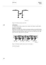
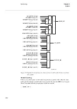
6LJQDO
BCABOPTR
Signal if there is no bus-coupler connection through the own bus coupler
between busbar A and B.
VPBCABTR
The switch status of BC_AB is valid.
EXDUP_BC
Signal if there is no transmission error from the bay that contains the above
information. This signal is taken from the data valid output on the command
function block.
Summary of Contents for REO 517
Page 10: ... RQWHQWV ...
Page 16: ...6 Introduction to the application manual KDSWHU QWURGXFWLRQ ...
Page 64: ...54 Blocking of signals during test KDSWHU RPPRQ IXQFWLRQV ...
Page 88: ...78 Scheme communication logic ZCOM KDSWHU LQH LPSHGDQFH ...
Page 146: ...136 Unbalance protection for capacitor banks TOCC KDSWHU XUUHQW ...
Page 166: ...156 Dead line detection DLD KDSWHU 3RZHU V VWHP VXSHUYLVLRQ ...
Page 378: ...368 Monitoring of DC analog measurements KDSWHU 0RQLWRULQJ ...
Page 384: ...374 Pulse counter logic PC KDSWHU 0HWHULQJ ...
Page 412: ...402 Serial communication modules SCM KDSWHU DWD FRPPXQLFDWLRQ ...
Page 440: ...430 LED indication module KDSWHU DUGZDUH PRGXOHV ...