


244
Interlocking
&KDSWHU
&RQWURO
6LJQDOVIURPEXVFRXSOHU
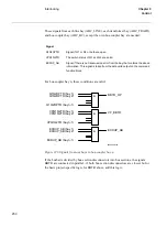
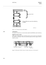
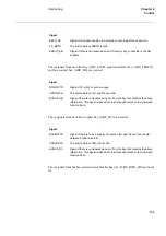
If the busbar is divided by bus-section disconnectors into bus sections, the busbar-bus-
bar connection could exist via the bus-section disconnector and bus-coupler within the
other bus section.
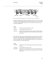
)LJXUH%XVEDUVGLYLGHGE\EXVVHFWLRQGLVFRQQHFWRUVFLUFXLWEUHDNHUV
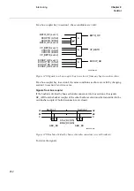
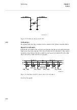
To derive the signals:
These signals from each bus-coupler bay (ABC_BC) are needed:
6LJQDO
BC_AB_CL
Signal if a bus-coupler connection exists between busbar A and B.
BC_AC_OP
Signal if there is no bus-coupler connection between busbar A and C.
BC_AC_CL
Signal if a bus-coupler connection exists between busbar A and C.
BC_BC_OP
Signal if there is no bus-coupler connection between busbar B and C.
BC_BC_CL
Signal if a bus-coupler connection exists between busbar B and C.
VP_BC_AB
The switch status of BC_AB is valid.
VP_BC_AC
The switch status of BC_AC is valid.
VP_BC_BC
The switch status of BC_BC is valid.
EXDUP_BC
Signal if there is no transmission error from bay BC (bus-coupler bay).
Section 1
Section 2
A1A2_DC(BS)
B1B2_DC(BS)
ABC_LINE
ABC_BC
ABC_LINE
ABC_BC
A1
B1
C
C
B2
A2
99000362.vsd
Summary of Contents for REO 517
Page 10: ... RQWHQWV ...
Page 16: ...6 Introduction to the application manual KDSWHU QWURGXFWLRQ ...
Page 64: ...54 Blocking of signals during test KDSWHU RPPRQ IXQFWLRQV ...
Page 88: ...78 Scheme communication logic ZCOM KDSWHU LQH LPSHGDQFH ...
Page 146: ...136 Unbalance protection for capacitor banks TOCC KDSWHU XUUHQW ...
Page 166: ...156 Dead line detection DLD KDSWHU 3RZHU V VWHP VXSHUYLVLRQ ...
Page 378: ...368 Monitoring of DC analog measurements KDSWHU 0RQLWRULQJ ...
Page 384: ...374 Pulse counter logic PC KDSWHU 0HWHULQJ ...
Page 412: ...402 Serial communication modules SCM KDSWHU DWD FRPPXQLFDWLRQ ...
Page 440: ...430 LED indication module KDSWHU DUGZDUH PRGXOHV ...