


289
Event function (EV)
&KDSWHU
/RJLF
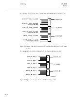
Each event function block has 16 connectables corresponding to 16 inputs INPUT1 to
INPUT16. Every input can be given a name with up to 19 characters from the CAP con-
figuration tool.
The inputs can be used as individual events or can be defined as double indication
events.
The inputs can be set individually from the Parameter Setting Tool (PST) under the
Mask-Event function as:
•
No events
•
OnSet, at pick-up of the signal
•
OnReset, at drop-out of the signal
•
OnChange, at both pick-up and drop-out of the signal
Also an input PrColxx (xx=01-44) is available on the function block to define on which
protocol the events shall be sent.
The event function blocks EV01-EV06 have inputs for information numbers and func-
tion type, which are used to define the events according to the communication standard
IEC 60870-5-103.
'RXEOHLQGLFDWLRQ
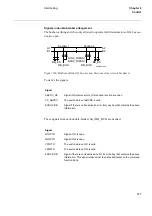
Double indications are used to handle a combination of two inputs at a time, for exam-
ple, one input for the open and one for the close position of a circuit breaker or discon-
nector. The double indication consists of an odd and an even input number. When the
odd input is defined as a double indication, the next even input is considered to be the
other input. The odd inputs has a suppression timer to suppress events at 00 states.
To be used as double indications the odd inputs are individually set from the SMS under
the Mask-Event function as:
•
Double indication
•
Double indication with midposition suppression
Here, the settings of the corresponding even inputs have no meaning.
These states of the inputs generate events. The status is read by the station HMI on the
status indication for the odd input:
•
00 generates an intermediate event with the read status 0
•
01 generates a close event with the read status 1
•
10 generates an open event with the read status 2
Summary of Contents for REO 517
Page 10: ... RQWHQWV ...
Page 16: ...6 Introduction to the application manual KDSWHU QWURGXFWLRQ ...
Page 64: ...54 Blocking of signals during test KDSWHU RPPRQ IXQFWLRQV ...
Page 88: ...78 Scheme communication logic ZCOM KDSWHU LQH LPSHGDQFH ...
Page 146: ...136 Unbalance protection for capacitor banks TOCC KDSWHU XUUHQW ...
Page 166: ...156 Dead line detection DLD KDSWHU 3RZHU V VWHP VXSHUYLVLRQ ...
Page 378: ...368 Monitoring of DC analog measurements KDSWHU 0RQLWRULQJ ...
Page 384: ...374 Pulse counter logic PC KDSWHU 0HWHULQJ ...
Page 412: ...402 Serial communication modules SCM KDSWHU DWD FRPPXQLFDWLRQ ...
Page 440: ...430 LED indication module KDSWHU DUGZDUH PRGXOHV ...