


121
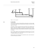
Thermal phase overload protection
(THOL)
&KDSWHU
&XUUHQW
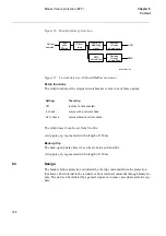
For other parameters: see description in the setting table in the Technical Reference
Manual.
6HWWLQJH[DPSOH
Assume the following data:
•
I1b: 5 A
•
Temperature increase of the conductor: 90°C at continuous load current 4.5 A.
•
Max. permissible temperature of the conductor: 125°C
•
Time constant
τ
= 20 min
•
Max. ambient temperature: 30°C
•
Max. temperature increase due to radiant power from the sun: 5°C
([2/ZLWKQRWHPSHUDWXUHFRPSHQVDWLRQ
I
base
= 4.5 A = 4.5/5 x 100 = 90% of I1b
T
base
= 90°C,
τ
= 20 min
The thermal function assumes 20°C ambient temperature as a fixed value instead of the
actual value 30°C. Also, the 5°C temperature increase due to the sun radiant power is
not included in the calculated temperature increase. Hence, the function calculates con-
tinuos conductor temperature 20 + 90 = 110°C at 4.5 A whereas the max. value is 30 +
90 +5 = 125°C. Hence the setting should be TTrip = 125 - (125 - 110) = 110°C.
([2/ZLWKWHPSHUDWXUHFRPSHQVDWLRQ
Assume temperature measuring elements with output 4 mA at -20°C and 20 mA at
100°C. Settings of Ibase, T
base
and
τ
same as above.
MI11-1_Max= 20.00mA MI11-MaxValue = +100°C
MI11-I_Min= 4.00mA MI11-MinValue = -20°C
The influence of the ambient temperature is included in the calculated values. The 5°C
temperature increase due to the sun radiant power, however, is not included. Hence the
setting should be T
trip
= 125 - 5 = 120°C.
The current transformer secondary setting current (Is
SEC
) is:
(Equation 58)
Is
SEC
I
S EC
I
PRIM
--------------
Is
⋅
=
Summary of Contents for REO 517
Page 10: ... RQWHQWV ...
Page 16: ...6 Introduction to the application manual KDSWHU QWURGXFWLRQ ...
Page 64: ...54 Blocking of signals during test KDSWHU RPPRQ IXQFWLRQV ...
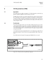
Page 88: ...78 Scheme communication logic ZCOM KDSWHU LQH LPSHGDQFH ...
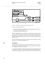
Page 146: ...136 Unbalance protection for capacitor banks TOCC KDSWHU XUUHQW ...
Page 166: ...156 Dead line detection DLD KDSWHU 3RZHU V VWHP VXSHUYLVLRQ ...
Page 378: ...368 Monitoring of DC analog measurements KDSWHU 0RQLWRULQJ ...
Page 384: ...374 Pulse counter logic PC KDSWHU 0HWHULQJ ...
Page 412: ...402 Serial communication modules SCM KDSWHU DWD FRPPXQLFDWLRQ ...
Page 440: ...430 LED indication module KDSWHU DUGZDUH PRGXOHV ...