


129
Breaker failure protection (BFP)
&KDSWHU
&XUUHQW
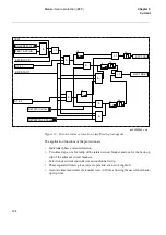
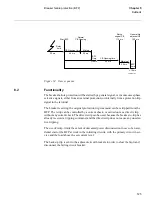
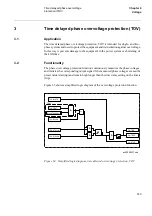
The operating values of the current measuring elements are settable within a wide set-
ting range. The measuring is stabilised against the dc-transient that can cause unwanted
operation at saturated current transformers and correct breaker operation. Time mea-
surement is individual for each phase. Two independent timers are available, t1 for re-
peated tripping of “own” breaker and t2 which operates trip logic for adjacent breakers.
&DOFXODWLRQV
6HWWLQJ
+XPDQPDFKLQHLQ0,
The parameters for the breaker failure protection function are set via the local HMI or
PST (Parameter Setting Tool). Refer to the Technical reference manual for setting pa-
rameters and path in local HMI.
The breaker-failure protection can be controlled from the human-machine interface
(HMI) by an “Operation” parameter, to be set between alternatives Off/On.
When “Operation” is set to Off, the function becomes inoperative.
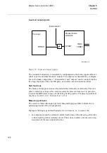
The configuration of input and output signals to the function is made with the CAP con-
figuration tool.
The inputs and the outputs to and from the breaker-failure protection are presented in
the signal list.
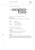
The breaker failure protection shall be set by means of a current limit for detection of a
breaker failure. The current setting shall be chosen in relation to the protection func-
tions, initiating the breaker failure protection. Normally the current setting should be
equal to or lower than the most sensitive setting of a residual overcurrent protection.
If the retrip function is used a time delay before retrip has to be set. In most cases this
time delay can be set to zero.
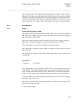
The time delay of the back-up trip function shall be chosen so that selectivity is main-
tained. Consider the following:
t1: Set retrip time delay
)L[HGYDOXHV
Trip pulse, tp
150 ms, fixed
Summary of Contents for REO 517
Page 10: ... RQWHQWV ...
Page 16: ...6 Introduction to the application manual KDSWHU QWURGXFWLRQ ...
Page 64: ...54 Blocking of signals during test KDSWHU RPPRQ IXQFWLRQV ...
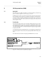
Page 88: ...78 Scheme communication logic ZCOM KDSWHU LQH LPSHGDQFH ...
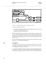
Page 146: ...136 Unbalance protection for capacitor banks TOCC KDSWHU XUUHQW ...
Page 166: ...156 Dead line detection DLD KDSWHU 3RZHU V VWHP VXSHUYLVLRQ ...
Page 378: ...368 Monitoring of DC analog measurements KDSWHU 0RQLWRULQJ ...
Page 384: ...374 Pulse counter logic PC KDSWHU 0HWHULQJ ...
Page 412: ...402 Serial communication modules SCM KDSWHU DWD FRPPXQLFDWLRQ ...
Page 440: ...430 LED indication module KDSWHU DUGZDUH PRGXOHV ...