


the inner rear cabinet wall. Cable contacts are of type DIN 41651.
31x External connection
The standard connections to the robot are with 64-pole plug-in connectors DIN 43652 on
the outer left-hand side of the control system (seen from the front).
XS2
IRB6000
XS2
1KB 2000 and 1KB
3000/3200
XB1
Fig 6.7 External connection
33x Screw connection
For customers who do not desire plug-in contacts there is the possibility of connecting
signals (apart from the robot's control signals) to various types of screw terminals. These
are mounted on the rear inner wall of the control system.
The screw terminal units are mounted on mounting plates provided with cable channels
and standard EN 50022 bars for attaching the screw terminal units.
The number of bars are matched to the options selected. In all, up to 5 bars can be
mounted; however, this is reduced to 4 with opt 145, flange disconnet switch.
Description
1KB 2000
48
Summary of Contents for IRB 2000
Page 8: ...Description 1KB 2000 ...
Page 10: ...Description 1KB 2000 ...
Page 12: ...Description 1KB 2000 6 ...
Page 20: ...Description 1KB 2000 14 ...
Page 32: ...Description 1KB 2000 26 ...
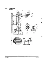
Page 40: ...5 3 2 Dimensional drawings Description 34 1KB 2000 ...
Page 41: ..._200 _D D_ Description 35 1KB 2000 ...
Page 44: ...Description 1KB 2000 38 ...
Page 64: ...Description 1KB 2000 58 ...
Page 77: ...Safety 1KB 2000 IBB 3000 12 1KB 3200 1KB 6000 ...
Page 80: ...Installation H B 2000 ...
Page 82: ...Installation 1KB 2000 ...
Page 91: ...Installation 1KB 2000 12 ...
Page 95: ...Installation 1KB 2000 16 ...
Page 110: ...INSTALLATION S3 0 4 ...
Page 112: ...INSTALLATION S3 1 2 ...
Page 160: ...INSTALLATION 3 46 ...
Page 234: ...INSTALLATION 5 70 ...
Page 262: ...INSTALLATION S3 7 6 ...


