


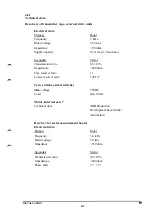


Status signals from the control system
(EXT MOTOR ON 1, 2, EXT BRAKE)
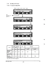
Max. supply voltage
Max. current continuously
Max. potential in relation to ground
Signal class according to section 3.1
48VDC
1A
400 V
control signals
6.3
Signal description
6.3.1
Common signals
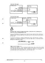
The following signals are for the external axes 7 -12:
LIM SW EXT(l-7)
The signal is common to all limit-position switches throughout the system. All limit-switches
are connected in series. An open circuit indicates that the external axis has reached the limit
of its working range, and this will tripthe safety chains in the robot. The signal must be
jumpered if not used. When the MOTOR ON-button in the control system is kept depressed,
the axis can be jogged past the limit-position switches back into working range.
Note: The dual safety chains requries on intermediate relay if a single limit switch is used.
Control system
XS3/XT3
EST0P1 A10
EXT LIM 1 A12
ESTOP 2 Bll
EXT LIM 2 B12
1
1
INSTALLATION
S3
6:4
Summary of Contents for IRB 2000
Page 8: ...Description 1KB 2000 ...
Page 10: ...Description 1KB 2000 ...
Page 12: ...Description 1KB 2000 6 ...
Page 20: ...Description 1KB 2000 14 ...
Page 32: ...Description 1KB 2000 26 ...
Page 40: ...5 3 2 Dimensional drawings Description 34 1KB 2000 ...
Page 41: ..._200 _D D_ Description 35 1KB 2000 ...
Page 44: ...Description 1KB 2000 38 ...
Page 64: ...Description 1KB 2000 58 ...
Page 77: ...Safety 1KB 2000 IBB 3000 12 1KB 3200 1KB 6000 ...
Page 80: ...Installation H B 2000 ...
Page 82: ...Installation 1KB 2000 ...
Page 91: ...Installation 1KB 2000 12 ...
Page 95: ...Installation 1KB 2000 16 ...
Page 110: ...INSTALLATION S3 0 4 ...
Page 112: ...INSTALLATION S3 1 2 ...
Page 160: ...INSTALLATION 3 46 ...
Page 234: ...INSTALLATION 5 70 ...
Page 262: ...INSTALLATION S3 7 6 ...


