Guide text
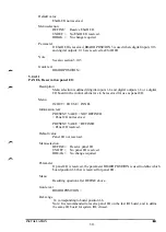
Al = Robot axis 1
A6 = Robot axis 6
A7 = External axis 7
A12 = External axis
Def. range
0 = The axis concerned has no brake.
1 = The axis concerned is equipped with a brake.
Default value
Al - A6 = 1 Axis brake.
A7-A12= 0 No axis brake.
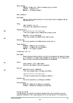
Warning
It is important that the system parameters for brakes are defined so that they
correspond to the actual brake equipment on the different axis. With incorrect
definitions, the following can happen when BRAKE ON is commanded in the
system after a time in the MOTOR ON mode with an inactive robot:
- If an axis without brake is defined with a brake (= 1), the robot can collapse
because the servo control is deactivated when the brakes are to be applied.
- If an axis with a brake is defined without a brake (= 0), the robot will go to
MOTOR OFF with a jam error because power is applied to the motor despite
the application of the brake.
Note for external axes 8-12 and external axis 7 with external drive unit: When
application of the brake is commanded, a common brake signal, EXT BRAKE
CONTROL connected to external axes with brakes is activated. This signal must
also be used to block the servo of the external axes to prevent the speed controller
from integrating up to the current limit. To avoid dipping when brakes are
applied, a time delay relay should be used on the signal to block the servo.
5.2.4.15
STATION (AW only)
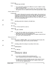
Sharing of external axes on stations.
Description
The parameter area STATION is used to distribute the external axes to the
stations to permit activation of the external axes in suitable groups. The stations
can be activated/deactivated independently except when axes share a common
drive unit. Six stations are available; A, B, C, D, E and F.
Menu
AXES + EXTAX + STATION
Information text
A NOT DEFINED
= station A is not defined
A*: INP11 OUTP1 AXES:7 12 ->
= station A consists of the axes 7 and 12, activated with output 1 and that the
activation is acknowledged at input 11. The asterisk indicates that the station is
to be synchronized separately from other asterisk-marked stations. The arrow
indicates that several stations are defined.
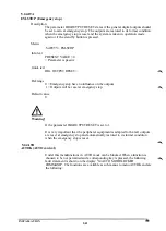
Note
All stations are normally undefined. Station A must be defined first before any other
station can be defined.
INSTALLATION S3
5:34
Summary of Contents for IRB 2000
Page 8: ...Description 1KB 2000 ...
Page 10: ...Description 1KB 2000 ...
Page 12: ...Description 1KB 2000 6 ...
Page 20: ...Description 1KB 2000 14 ...
Page 32: ...Description 1KB 2000 26 ...
Page 40: ...5 3 2 Dimensional drawings Description 34 1KB 2000 ...
Page 41: ..._200 _D D_ Description 35 1KB 2000 ...
Page 44: ...Description 1KB 2000 38 ...
Page 64: ...Description 1KB 2000 58 ...
Page 77: ...Safety 1KB 2000 IBB 3000 12 1KB 3200 1KB 6000 ...
Page 80: ...Installation H B 2000 ...
Page 82: ...Installation 1KB 2000 ...
Page 91: ...Installation 1KB 2000 12 ...
Page 95: ...Installation 1KB 2000 16 ...
Page 110: ...INSTALLATION S3 0 4 ...
Page 112: ...INSTALLATION S3 1 2 ...
Page 160: ...INSTALLATION 3 46 ...
Page 234: ...INSTALLATION 5 70 ...
Page 262: ...INSTALLATION S3 7 6 ...


