


3.11.2
Analog Connections
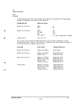
The connection table below presents the connection between physical inputs/outputs and ports:
Signal name Function Terminal Notes
INPUT CHI
INPUT CH 2
INPUT CH 3
INPUT CH 4
OV
OV
OUTPUT CH 1
OUTPUT CH 2
OUTPUT CH 3
OUTPUT CH 4
OV
OV
EXT+15V
EXT+15V
EXT-15 V
EXT-15 V
OV
OV
XS10
0 - ±10 V max. 10 Hz B3
0 - ±10 V max. 10 Hz A3
0 - ±10 V max. 100 Hz D3
0 - ±10 V max. 100 Hz C3
Return analog input B4
Return analog input A4
0 - ±10 V min. 8 kohm D4
0-±10Vmin. 4kohm C4
0 - ±10 V min. 2 kohm B5
0 - ±20 mA max. 450 ohm D5
Return analog output A5
Return analog output
External 15 V
External 15 V
External supply -15 V
External supply -15 V
0 V external supply
0 V external supply
C5
B6
A6
B7
A7
D6
C6
XT10
2 Port 31
I Port 32
4 Port 33
3 Port 34
6 Internally connected to A4(5)
5 Internally connected to B46)
8 Port 21 Normally voltage
reference in AW-systems
7 Port 22 Normally current
reference in AW-systems
10 Port 23
12 Port 24
9 Internally connected to C5(ll)
II Internally connected to A5(9)
14 +15 V supply of analog I/O
Internally connected to A6(13)
13 +15 V supply of analog I/O.
Internally connected to B6(14)
18 -15 V supply of analog I/O.
Internally connected to A7(17)
17 -15 V supply of analog I/O.
Internally connected to B7(18)
16 0 V supply of analog I/O.
Internally connected to C6(15)
15 0 V supply of analog I/O.
Internally connected to D6(16)
The following applies with internal supply:
There is no galvanic isolation from the control cabinet electronics.
The in15 V, -15 V and 0 V are available at the same contact (duplicated with internal
connector) and must be strapped to the corresponding terminal for external voltages.
The in15 V, -15 V and 0 V may only be used for voltage supply of the analog I/O board.
INT+15 V
INT+15 V
INT-15 V
INT-15 V
OV
OV
Internal 15 V
Internal 15 V
Internal supply -15 V
Internal supply -15 V
OV
OV
D l l
C l l
B12
A12
D12
C12
36
35
38
37
40
39
Strapped to a B6
and/or A6(14,13)
Strapped to a B6
and/or A6(14,13)
Strapped to a B7
and/or A7(18,17)
Strapped to a B7
and/or A7(18,17)
Strapped to D6
and/orC6(16,15)
Strapped to D6
and/or C6 (16,15)
INSTALLATION
3:32
S3
Summary of Contents for IRB 2000
Page 8: ...Description 1KB 2000 ...
Page 10: ...Description 1KB 2000 ...
Page 12: ...Description 1KB 2000 6 ...
Page 20: ...Description 1KB 2000 14 ...
Page 32: ...Description 1KB 2000 26 ...
Page 40: ...5 3 2 Dimensional drawings Description 34 1KB 2000 ...
Page 41: ..._200 _D D_ Description 35 1KB 2000 ...
Page 44: ...Description 1KB 2000 38 ...
Page 64: ...Description 1KB 2000 58 ...
Page 77: ...Safety 1KB 2000 IBB 3000 12 1KB 3200 1KB 6000 ...
Page 80: ...Installation H B 2000 ...
Page 82: ...Installation 1KB 2000 ...
Page 91: ...Installation 1KB 2000 12 ...
Page 95: ...Installation 1KB 2000 16 ...
Page 110: ...INSTALLATION S3 0 4 ...
Page 112: ...INSTALLATION S3 1 2 ...
Page 160: ...INSTALLATION 3 46 ...
Page 234: ...INSTALLATION 5 70 ...
Page 262: ...INSTALLATION S3 7 6 ...


