3.6
Voltage supply to electronics
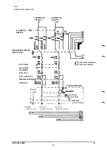
The system is provied with a 24 V supply for internal use, 24 V I/O.
3.6.1
24 V I/O
This voltage is used internally for the robot brakes supply, and MOTOR ON circuits. It's
OV is common to other electronics supplyin the control system.
Techical data
Voltage 24,0 V-26.4 V
Ripple max. 0,5 V p-p
Permitted user load max. 4 A
Current at shortage max. 5 A (average value)
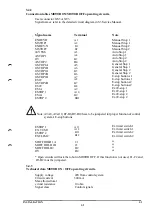
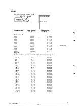
Voltage is available to the user in accordance with the following connection table:
User's connector: User's connector:
XS3 eller XT3 XT18
Signal name Terminal Signal name Terminal
24 V I/O A15,B15 24V I/O 13,14,15,16
24 V I/O A16.B16 24V I/O 29,30,31,32
24 V I/O C16
0VI/O C14,D14 0VI/O 5,6,7,8
0VI/O C15.D15 0VI/O 21,22,23,24
0VI/O D16
3.6.2
External supply
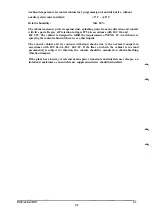
External supply is to be used in the following cases:
• The internal supply provides too little current.
• Galvanic isolation is necessary because of the risk of interference through ground
currents.
• Galvanic isolation is necessary because of the difference in potential between the
control signal and the chassis ground.
• Galvanic isolation is required for reasons of safety.
• Risk of the transmission of considerable interference into the internal 24 V supply.
External supply is recommended to utilize the the galvanic isolation of the I/O-boards.
This could result in disturbances in the normal operations of the control cabinet.
The zero of the external supply must be connected in such a way that the maximum
permissible potential difference between the zero and chassis ground is not exceeded i.e.
by connecting a zero conductor to the chassis ground or some other common grounding
point
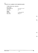
Technical data:
Potential difference to chassis ground: max. 60 V continously
max. 500 V for 1 minute
Permissible supply voltage: 19 - 35 V including ripple
INSTALLATION S3
3:13
Summary of Contents for IRB 2000
Page 8: ...Description 1KB 2000 ...
Page 10: ...Description 1KB 2000 ...
Page 12: ...Description 1KB 2000 6 ...
Page 20: ...Description 1KB 2000 14 ...
Page 32: ...Description 1KB 2000 26 ...
Page 40: ...5 3 2 Dimensional drawings Description 34 1KB 2000 ...
Page 41: ..._200 _D D_ Description 35 1KB 2000 ...
Page 44: ...Description 1KB 2000 38 ...
Page 64: ...Description 1KB 2000 58 ...
Page 77: ...Safety 1KB 2000 IBB 3000 12 1KB 3200 1KB 6000 ...
Page 80: ...Installation H B 2000 ...
Page 82: ...Installation 1KB 2000 ...
Page 91: ...Installation 1KB 2000 12 ...
Page 95: ...Installation 1KB 2000 16 ...
Page 110: ...INSTALLATION S3 0 4 ...
Page 112: ...INSTALLATION S3 1 2 ...
Page 160: ...INSTALLATION 3 46 ...
Page 234: ...INSTALLATION 5 70 ...
Page 262: ...INSTALLATION S3 7 6 ...


