


Feedback
Resolver specification: 1st resolver ratio 1:1
2nd resolver ratio 136:137
Resolver of transmitter type
Voltage ratio 2:1 (rotor:stator)
Excitation: To one or two resolvers and to
synchronising switch.
Excitation voltage 5.7 V/2 kHz
200 I/O CAPACITY
I/O units are not included in the basic versions of IRB 2000.
In all, there are 6 available I/O slots (max. 5 with option 405 Winchester memory included):
• digital I/O, 16 in/16 out, max. 6 units (1 slot per unit)
• analogue I/O, 4 in/4 out, max. 1 unit (1 slot)
• AD combined I/O, digital 16 in/ 16 out and analogue 2 out, max. 1 unit
( 1 slot)
• RIO remote link for Allen Bradley PLC, max. 1 unit (2 slots)
With regard to analogue and combined I/O, only one of the units can be used in the system at
the same time.
20X Digital I/O
Digital I/O unit
Inputs: 16 opto-connected
Rated voltage: 24 V DC
Current at rated input voltage: 5.5 mA
Outputs: 16 opto-connected, short circuit protected
Rated voltage: 24 V DC
Load capacity per output: 200 mA
Load capacity per group of 8 outputs: 1A
The unit is electrically divided into 4 parts, with 8 inputs or outputs in each part.
Each part requires a separate voltage supply as follows in accordance with one of
the following alternatives:
• Internal supply from the control system, not galvanically insulated from
the electronics in the cabinet.
• External supply, galvanically insulated from the electronics in the cabinet.
Voltage range 19-35 V DC.
Connection points for the internal and the external supplies are provided in the system.
Reserved I/O groups.
Four groups of digital I/O may be reserved via the system parameters:
system I/O
remote control
weldequipment (AW)
drive units (AW)
gripper 3-8 (GL, MH/ASST)
digital gluing I/O
SWI (GL, MH/ASS'Y)
Contents and effects of reservations are described below.
Description D3B 2000
42
Summary of Contents for IRB 2000
Page 8: ...Description 1KB 2000 ...
Page 10: ...Description 1KB 2000 ...
Page 12: ...Description 1KB 2000 6 ...
Page 20: ...Description 1KB 2000 14 ...
Page 32: ...Description 1KB 2000 26 ...
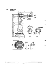
Page 40: ...5 3 2 Dimensional drawings Description 34 1KB 2000 ...
Page 41: ..._200 _D D_ Description 35 1KB 2000 ...
Page 44: ...Description 1KB 2000 38 ...
Page 64: ...Description 1KB 2000 58 ...
Page 77: ...Safety 1KB 2000 IBB 3000 12 1KB 3200 1KB 6000 ...
Page 80: ...Installation H B 2000 ...
Page 82: ...Installation 1KB 2000 ...
Page 91: ...Installation 1KB 2000 12 ...
Page 95: ...Installation 1KB 2000 16 ...
Page 110: ...INSTALLATION S3 0 4 ...
Page 112: ...INSTALLATION S3 1 2 ...
Page 160: ...INSTALLATION 3 46 ...
Page 234: ...INSTALLATION 5 70 ...
Page 262: ...INSTALLATION S3 7 6 ...


