


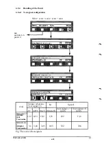


User contact XS7
LIM1M7
LIMIT1
LIM2M7
LIMIT 2
PTCM7B
0VPTCM7
24VI/O
OV
BRAKE RESLEASE M7
M17
M27
M37
A4
A5
B4
B5
D2
Dl
A10
BIO
A9
A1.A2
B1,B2
C1.C2
A4-A5, B4-B5 jumpered
if not used
D2-D1 jumpered
if not used
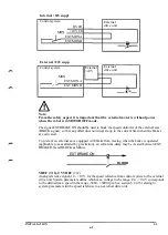
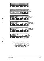
External axes 7-12
As well as the signals described in section 6.3.1, the following control signals shall be
connected between control systemt and external drive units:
EXT MON 1A-1B and 2A -2B
Orders MOTOR ON/MOTOR OFF status in the control system to the common logic for external
axes. Closed loop indicates that the control system is in MOTOR ON mode (voltage to motors).
Open loop indicates MOTOR OFF mode (no motor voltage).
EXT BRAKE ON
Orders BRAKE ON/BRAKE OFF from control system. Closed loop indicates that the robot
brakes are not engaged, i.e. the motors retain the robot arms in position.
Incorrect definition of the system parameters with respect to brakes or external
axes may result in hazardous conditions.
INSTALLATION S3
6:8
Summary of Contents for IRB 2000
Page 8: ...Description 1KB 2000 ...
Page 10: ...Description 1KB 2000 ...
Page 12: ...Description 1KB 2000 6 ...
Page 20: ...Description 1KB 2000 14 ...
Page 32: ...Description 1KB 2000 26 ...
Page 40: ...5 3 2 Dimensional drawings Description 34 1KB 2000 ...
Page 41: ..._200 _D D_ Description 35 1KB 2000 ...
Page 44: ...Description 1KB 2000 38 ...
Page 64: ...Description 1KB 2000 58 ...
Page 77: ...Safety 1KB 2000 IBB 3000 12 1KB 3200 1KB 6000 ...
Page 80: ...Installation H B 2000 ...
Page 82: ...Installation 1KB 2000 ...
Page 91: ...Installation 1KB 2000 12 ...
Page 95: ...Installation 1KB 2000 16 ...
Page 110: ...INSTALLATION S3 0 4 ...
Page 112: ...INSTALLATION S3 1 2 ...
Page 160: ...INSTALLATION 3 46 ...
Page 234: ...INSTALLATION 5 70 ...
Page 262: ...INSTALLATION S3 7 6 ...


