4.1.1 Remote control
• By using the first 8 inputs and outputs on any I/O board the following functions can
be remotely controlled:
Control Indication
(input) (output)
MOTOR ON X X
MOTOR OFF X X
Program start X X
Program stop X X
Synchronization X X
From disc X X
Lamp test X
Prog, unit lock X
Error X
Emergency stop X
4.2 Programming unit
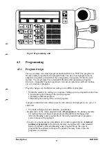
The programming unit (Fig. 4.2) is connected to the control system by a 10 m cable
(extension cable 10 m, total 30 m, option). When not in use, it is placed on a consol
on the door of the control system.
The programming unit is provided with LED displays and membrane buttons with
tactile feedback. The enabling device is located under the emergency stop button.
The enabling device allows the operator to switch between MOTOR ON and
MOTOR OFF when the operating mode selector is in one of the MANUAL
positions.
All operator communications, except selection of the operational mode for the
robot, are available on the portable programming unit. The programming unit is
provided with the following facilities for this purpose:
• An illuminated two-row alphanumeric display for messages in plain language.
The system can display:
- texts in any of 10 languages: English, German, French, Dutch, Italian,
Spanish, Portuguese, Japanese(Katakana) Finnish and Swedish;
- numerical values in metric or imperial.
• Five multi-function buttons below the panel.
The text on the lower row of the display defines the use of the multi-function buttons.
• Six to eight menus for most of the system functions.
Each menu contains a particular type of function, e.g. program editing.
• Joystick
The robot and the external axis are positioned using the joystick, together
with the safety pad and the switches in the upper right-hand corner.
Description 1KB 2000
16
Summary of Contents for IRB 2000
Page 8: ...Description 1KB 2000 ...
Page 10: ...Description 1KB 2000 ...
Page 12: ...Description 1KB 2000 6 ...
Page 20: ...Description 1KB 2000 14 ...
Page 32: ...Description 1KB 2000 26 ...
Page 40: ...5 3 2 Dimensional drawings Description 34 1KB 2000 ...
Page 41: ..._200 _D D_ Description 35 1KB 2000 ...
Page 44: ...Description 1KB 2000 38 ...
Page 64: ...Description 1KB 2000 58 ...
Page 77: ...Safety 1KB 2000 IBB 3000 12 1KB 3200 1KB 6000 ...
Page 80: ...Installation H B 2000 ...
Page 82: ...Installation 1KB 2000 ...
Page 91: ...Installation 1KB 2000 12 ...
Page 95: ...Installation 1KB 2000 16 ...
Page 110: ...INSTALLATION S3 0 4 ...
Page 112: ...INSTALLATION S3 1 2 ...
Page 160: ...INSTALLATION 3 46 ...
Page 234: ...INSTALLATION 5 70 ...
Page 262: ...INSTALLATION S3 7 6 ...


