


3.11
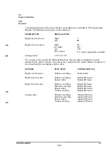
Analog I/O (option)
One analog I/O board can be placed at board position 1. A board is available for analog
inputs/outputs with:
• 4 inputs for 0 - ±10 V
• 3 voltage outputs for 0 - ±10 V
• 1 current output for 0 - ±20 mA
As a alternative is a combined I/O board available, see 3.11.3.
The inputs and outputs belong to a common group which is galvanically isolated from the
electronics of the control cabinet. The analog I/O-board is placed on I/O-board position
KD26.168) but connected to a separate contact.
The analog inputs and outputs in the robot system can be supplied with an internal ±15 V
voltage from the control cabinet or with an external ±15 V voltage. When internal ±15 V
voltage is used, there is no galvanic isolation between the analog inputs/outputs and the
control cabinet electronics.
The function of the analog I/O board is shown in principle in the following figure:
Control
program
D/A-
convertor
id
A/D-
convertor
0 V-signal
+15V EXT
-15 V EXT
OVEXT
" • +15 VINT
- • -15 VINT
OVINT
INSTALLATION
3:30
Summary of Contents for IRB 2000
Page 8: ...Description 1KB 2000 ...
Page 10: ...Description 1KB 2000 ...
Page 12: ...Description 1KB 2000 6 ...
Page 20: ...Description 1KB 2000 14 ...
Page 32: ...Description 1KB 2000 26 ...
Page 40: ...5 3 2 Dimensional drawings Description 34 1KB 2000 ...
Page 41: ..._200 _D D_ Description 35 1KB 2000 ...
Page 44: ...Description 1KB 2000 38 ...
Page 64: ...Description 1KB 2000 58 ...
Page 77: ...Safety 1KB 2000 IBB 3000 12 1KB 3200 1KB 6000 ...
Page 80: ...Installation H B 2000 ...
Page 82: ...Installation 1KB 2000 ...
Page 91: ...Installation 1KB 2000 12 ...
Page 95: ...Installation 1KB 2000 16 ...
Page 110: ...INSTALLATION S3 0 4 ...
Page 112: ...INSTALLATION S3 1 2 ...
Page 160: ...INSTALLATION 3 46 ...
Page 234: ...INSTALLATION 5 70 ...
Page 262: ...INSTALLATION S3 7 6 ...


