


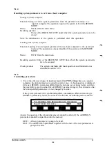


3.17
I/O signals - SWI (Spot Welding, Interface)
On the I/O board DSQC 223 some input and output signals are used for the SWI function, see
the figure below. All inputs, however, are still freely programmable and within reach under
the MANUAL button. The outputs are also programmable as usual but it is not possible to
control them under the MANUAL button.
The GRIP 1 and GRIP 2 signals are used to control both the working stroke and the opening
stroke of the first gun . These signals have therefore also been put on the same board as all the
other SWI signals. GRIP 1 and GRIP 2 are also available if you have an I/O system.
If a double gun is used, GRIP 3 and GRIP 4 are used for the working stroke and, opening
stroke, respectively, of gun two. These output signals are then defined in the usual way in the
functional parameters.
An example of reserved inputs and outputs for the SWI function, if the board is placed in the
second space.
Flexibel I/O
INPUT
1
2
3
4
5
6
WELD READY
TIMER OK
CURRENT OK
FLOW OK
TEMP OK
ENABLE MOVE
OUTPUT
1
2
3
4
5
6
7
8
START 1
START2
CURRENT ENABLE
WELD POWER
RESET
GRIP1
GRIP 2
PARITY
no.
17
18
19
20
21
22
23
24
17
18
19
20
21
22
23
24
cl
1
2
3
4
5
6
7
8
1
2
3
4
5
6
7
8
ch
no.
9
10
11
12
13
14
15
16
9
10
11
12
13
14
15
16
25
26
27
28
29
30
31
32
25
26
27
28
29
30
31
32
WELD PROGRAM " 1 *
WELD PROGRAM "2"
WELD PROGRAM "4"
WELD PROGRAM "8"
WELD PROGRAM "16
For more information, see Programming Manual.
NOTE 1. If flexible I/O (I/O-MAP) are used, are SWI-input every time 1 - 6 and SWI-output
1 - 1 3 see table independence of wher SWI-board is defin. This in- and output must be defined
in I/O MAP.
Note 2. Reserved input signals that are not used must be strapped to 24 V. This does not apply
to WELD READY, which has to be supplied from the welding controller (see above) to make it
possible to execute the SWI -instruction.
INSTALLATION
3:45
Summary of Contents for IRB 2000
Page 8: ...Description 1KB 2000 ...
Page 10: ...Description 1KB 2000 ...
Page 12: ...Description 1KB 2000 6 ...
Page 20: ...Description 1KB 2000 14 ...
Page 32: ...Description 1KB 2000 26 ...
Page 40: ...5 3 2 Dimensional drawings Description 34 1KB 2000 ...
Page 41: ..._200 _D D_ Description 35 1KB 2000 ...
Page 44: ...Description 1KB 2000 38 ...
Page 64: ...Description 1KB 2000 58 ...
Page 77: ...Safety 1KB 2000 IBB 3000 12 1KB 3200 1KB 6000 ...
Page 80: ...Installation H B 2000 ...
Page 82: ...Installation 1KB 2000 ...
Page 91: ...Installation 1KB 2000 12 ...
Page 95: ...Installation 1KB 2000 16 ...
Page 110: ...INSTALLATION S3 0 4 ...
Page 112: ...INSTALLATION S3 1 2 ...
Page 160: ...INSTALLATION 3 46 ...
Page 234: ...INSTALLATION 5 70 ...
Page 262: ...INSTALLATION S3 7 6 ...


