


4.2
Check list before startup
Before switching on the power, check as follows:
1. The mains supply fused rating.
2. The supply transformer in the cabinet is connected for the correct voltage.
3. The unused circuits in the safetychains must be closed by connecting jumpering:
Auto Stop: XS3 or XT3 A3 - A4 and B3 - B4
Manual Stop: XS3 or XT3 Al - A2 and Bl - B2
General Stop: XS3 or XT3 A5 - A6 and B5 - B6
Customer emergency stop XS3 or XT3 A7 - A8 and B7 - B8,
A9-A10and B9-B10
MOTOR OFF clamping device XS3orXT3 Cl - C2 and Dl - D2
External axes limit switches: XS3orXT3 All - A12 a n d B l l - B12
Extdrive units POWER OK: XS3 or XT3 C12 - C16
4. If the controller includes the external axes option, check that the external axes
connections are made, or the following circuits are jumpered:
Motor PTC, axis 7: XS7 Dl - D2
7th(- 12th) axes limit switches: XS7 A4 - A5 and B4 - B5
5. The programming unit is connected.
6. The operation modeselector on the operating panel is set to MANUAL
<250 mm/s.
4.3
Startup to standby
1. Make sure the cabinet door is closed
2. Switch the power on.
3. The MOTOR OFF lamp on the control panel illuminates when the system has completed
the hardware and software diagnostic test. This test
lasts about 30 seconds.
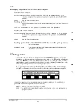
The following may occur after the start up routine is completed:
A. Normal start with presentation of the message " ABB ROBOT SYSTEM AT
YOUR SERVICE".
B. Presentation of a fault message.
If the MOTOR OFF- lamp flashes, read the error message on the programming unit display.
Actions to be taken to correct different errors are described in separate sections in the
Programming Manual or the Service Manual. Correct the cause of the fault message and
continue the start procedure as in case 1 above.
C. System parameters absent
See the chapter "System parameters".
INSTALLATION S3
4:3
Summary of Contents for IRB 2000
Page 8: ...Description 1KB 2000 ...
Page 10: ...Description 1KB 2000 ...
Page 12: ...Description 1KB 2000 6 ...
Page 20: ...Description 1KB 2000 14 ...
Page 32: ...Description 1KB 2000 26 ...
Page 40: ...5 3 2 Dimensional drawings Description 34 1KB 2000 ...
Page 41: ..._200 _D D_ Description 35 1KB 2000 ...
Page 44: ...Description 1KB 2000 38 ...
Page 64: ...Description 1KB 2000 58 ...
Page 77: ...Safety 1KB 2000 IBB 3000 12 1KB 3200 1KB 6000 ...
Page 80: ...Installation H B 2000 ...
Page 82: ...Installation 1KB 2000 ...
Page 91: ...Installation 1KB 2000 12 ...
Page 95: ...Installation 1KB 2000 16 ...
Page 110: ...INSTALLATION S3 0 4 ...
Page 112: ...INSTALLATION S3 1 2 ...
Page 160: ...INSTALLATION 3 46 ...
Page 234: ...INSTALLATION 5 70 ...
Page 262: ...INSTALLATION S3 7 6 ...


