196 Actual signals and parameters
1608 START
ENABLE 1
Selects the source for the Start enable 1 signal.
Note:
Functionality of the Start enable signal is different
from the Run enable signal.
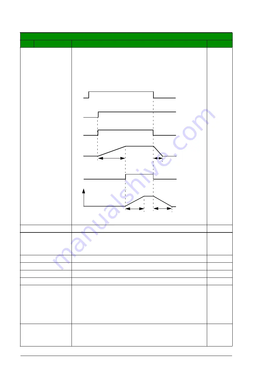
Example:
External damper control application using Start
enable and Run enable. Motor can start only after the
damper is fully open.
NOT SEL
Start enable signal is on.
0
DI1
External signal required through digital input DI1. 1 = Start
enable. If Start enable signal is switched off, the drive does
not start or it coasts to stop if it is running and alarm
is activated
1
DI2
See selection
.
2
DI3
See selection
.
3
DI4
See selection
.
4
DI5
See selection
.
5
COMM
Fieldbus interface as the source for the inverted Start
enable (Start disable) signal, ie Control word
bit 18 (bit 19 for Start enable 2). The Control word
is sent by the fieldbus controller through the embedded
fieldbus (Modbus) to the drive. For the Control word bits,
.
Note:
This setting applies only for the DCU profile.
7
DI1(INV)
External signal required through inverted digital input DI1. 0
= Start enable. If Start enable signal is switched off, the
drive does not start or it coasts to stop if it is running and
alarm
is activated.
-1
All parameters
No.
Name/Value
Description
Def/FbEq
Drive started
Start enable
signals
and
)
Started
output status
(group 14)
Damper
opening
time
Damper
closed
Damper
closing
time
Damper
status
Relay energized
Damper open
Relay
de-
energized
Damper
closed
Motor
status
Run enable signal
from the damper end
switch when the
damper is fully
opened. (
)
Acceleration
time (
Deceleration
time (
)
Motor
speed
Start/Stop
command
(group 10)
Aotewell Ltd
www.aotewell.com
Industry Automation
HongKong|UK|China
+86-755-8660-6182


