2-15
SPEC
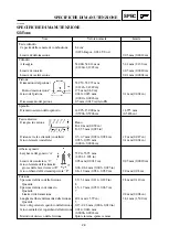
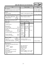
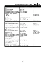
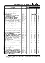
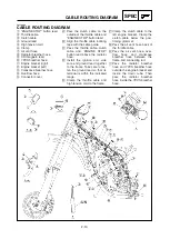
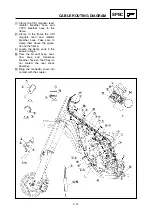
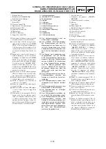
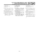
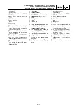
CABLE ROUTING DIAGRAM
1
High tension cord
2
“ENGINE STOP” button lead
3
Ignition coil lead
4
Clamp
5
CDI unit
6
CDI unit band
7
Radiator breather hose
8
CDI magneto lead
9
Connector cover
0
Throttle cable
q
Clutch cable
w
CDI unit stay
A
Pass the high tension cord to
the left of the radiator hose.
B
Using a plastic locking tie,
clamp the “ENGINE STOP”
button lead, ignition coil lead
and CDI magneto lead togeth-
er with the clamp ends back-
ward and then cut off the tie
end.
C
Clamp to the frame the throttle
cable, clutch cable, ignition coil
lead and “ENGINE STOP” but-
ton lead. In so doing, clamp
the ignition coil lead and
“ENGINE STOP” button lead at
their protecting tubes. Tighten
the clamp so that the “ENGINE
STOP” button lead is not
pulled when the handlebar is
turned to the right and left.
D
Pass the CDI magneto lead
and radiator breather hose
between the frame and the
radiator(right).
E
Clamp the CDI magneto lead
to the frame at its locating
tape.
F
Bring the connector cover into
contact with the coupler.
G
Locate the clamp ends in the
arrowed range.
H
Insert the CDI unit band until it
stops at the CDI unit stay.
I
Pass the CDI magneto lead
and radiator breather hose
between the frame and the
radiator hose so that they
come within the arrow-indicat-
ed range. Also take care so
that the CDI magneto lead
passes on the left of the radia-
tor breather hose.
1C3-9-32-2B 4/29/06 10:16 AM Page 30

