iv
9
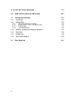
Error Code Screen Messages
9-1
10
Spare Parts and Service Information
10-1
11
Technical Assemblies
11-1
11.1
Front Panel
11-1
11.2
Syringe Plate
11-2
11.2.1
Internal Standard Valve Assembly
11-3
11.2.2
Mixing Solenoids / 26 mL Syringe Assembly
11-4
11.2.3
Probe Section
11-5
11.2.4
Vial Sample Stations
11-6
11.3
Interface / Transfer Line, Purge Gas Solenoid
11-7
11.4
Rear Panel
11-8
11.5
Robotic Arm
11-9
11.6
Interconnect Diagram
11-10
12
Flow Diagrams
12-1
Содержание archon
Страница 43: ...4 6 ...
Страница 73: ...6 18 ...
Страница 103: ...9 4 ...
Страница 117: ...11 10 11 6 Interconnect Diagram Note F R L R and U D P O T should be set at 3 4 std valve full power ...
Страница 119: ...12 2 ...


