2-18
2.11.3 Archon to OI 4560
Remove the installation and accessory kits from the shipping carton. Examine the
contents and verify all items are correct. The Archon may be positioned on either
the right or left side of the OI 4560.
WA R N IN G :
S H O C K H A ZA R D
Be certain both the Archon and the OI 4560 are turned OFF
and the power cords are disconnected before starting the
installation!
Remove the accessory kit from its shipping carton. Examine the contents and
verify all items are correct.
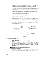
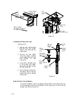
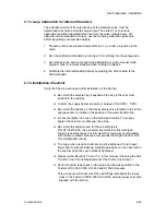
Installation of the Heated Soil Transfer Line to the OI 4560
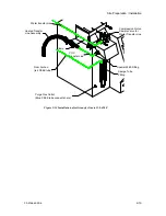
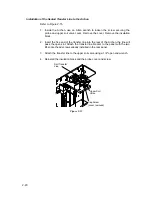
Refer to Figure 2-14.
1. Remove the plug installed in the AS port on the side of the OI 4560 sparge
tube mount.
2. Slide the heated transfer line assembly through the two clamps. Attach the
clamps, with line, to the bracket using the #6-32 x 1/2" screws with nuts and
lock washers.
3. Slide the special fitting (P/N DY-505727-00), provided in the Installation Kit,
onto the transfer line. Carefully bend the line and insert it, with the fitting, into
the AS port on the OI 4560. With a 5/16" wrench, tighten the larger nut first.
Push the line into the fitting and tighten the 1/4" nut.
4. Check all fittings and screws to ensure they are tight.
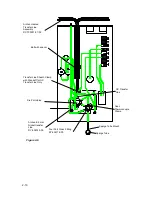
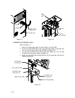
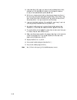
Installation of Purge Gas Lines
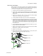
Refer to Figure 2-14.
1. Remove the OI 4560 purge gas line from the sparge tube and the outlet port
on the front of the 4560.
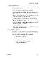
2. Connect the blue PEEK tube to the purge gas outlet on the OI 4560. Use
1/16” nut and ferrules for this connection.
3. Connect the red PEEK tube to the sparge tube fitting. Use 1/16” nut and
ferrules for this connection.
4. Route the peek tubing lines through the notch in the rear panel of the Archon
labeled “waste lines.”
Содержание archon
Страница 43: ...4 6 ...
Страница 73: ...6 18 ...
Страница 103: ...9 4 ...
Страница 117: ...11 10 11 6 Interconnect Diagram Note F R L R and U D P O T should be set at 3 4 std valve full power ...
Страница 119: ...12 2 ...

