2-16
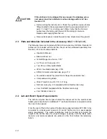
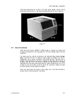
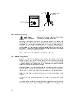
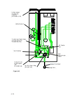
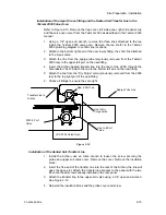
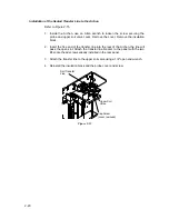
Figure 2-11
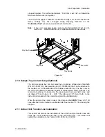
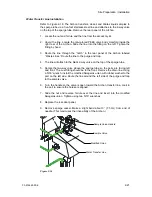
Figure 2-12
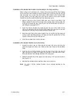
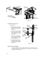
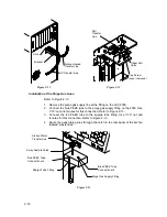
Installation of the Purge Gas Lines
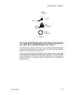
Refer to Figure 2-13.
1. Remove the purge gas supply line at the fitting on the LSC 2000.
2. Connect the blue PEEK tube to the purge gas supply fitting on the 2000. Use
1/16” nut and ferrules for this connection. Refer to Figure 2-13.
3. Connect the red PEEK tube to the sparge tube fitting. Use 1/16” nut and
ferrules for this connection. Refer to Figure 2-13.
4. Route the peek tubing lines through the notch in the rear panel of the Archon
labeled “waste lines”.
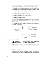
Figure 2-13
Soil
Transfer
Line
Cap Screw
(cover removed)
Upper Soil
Valve
Hole
Archon Heated
Transfer Line
Bracket
GC Transfer Line
Archon Water
Transfer Line
2-way Sample Valve
Blue PEEK Tube
Connects here
Red PEEK Tube
Connects here
Sparge Tube Fitting
Purge Gas Supply Fitting
Содержание archon
Страница 43: ...4 6 ...
Страница 73: ...6 18 ...
Страница 103: ...9 4 ...
Страница 117: ...11 10 11 6 Interconnect Diagram Note F R L R and U D P O T should be set at 3 4 std valve full power ...
Страница 119: ...12 2 ...

