2-12
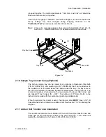
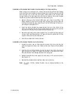
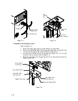
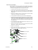
Figure 2-7
Figure 2-8
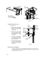
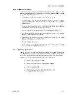
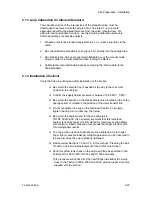
Installation of Purge Gas Lines
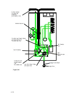
See Figure 2-9.
1. Remove the current purge
gas line from the “Purge”
fitting on the 3000 and the
sparge tube.
2. Connect the blue PEEK
tube to the “purge” out fitting
on the 3000. Use 1/16” nut
and ferrules for this
connection.
3. Connect the red PEEK tube
to the sparge tube fitting.
Use 1/16” nut and ferrules
for this connection.
4. Route the peek tubing lines
through the notch in the rear
panel of the Archon labeled
“waste lines”.
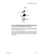
Figure 2-9
Water Transfer Line Installation
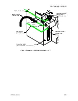
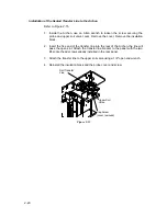
The Archon transfers, cleans, and dilutes liquid samples to the sparge tube via a
five-foot stainless steel line and attaches to the 2-way valve on the top of the
sparge tube. Refer to Figure 2-9.
Soil
Transfer
Line
Cap Screw
(cover removed)
Upper Soil
Valve
Tekmar Heated
GC Transfer
Line Assembly
Heated
Transfer Line
Channel
Archon Heated
Transfer Line
Assembly
Sparge Tube
Fitting
Red PEEK
Tube Connects
Here
Blue PEEK
Tube Connects
Here
2-Way
Sample
Valve
½” SS
Nut
Reverse
Ferrule
Fitting
Water
Transfer
Line
Содержание archon
Страница 43: ...4 6 ...
Страница 73: ...6 18 ...
Страница 103: ...9 4 ...
Страница 117: ...11 10 11 6 Interconnect Diagram Note F R L R and U D P O T should be set at 3 4 std valve full power ...
Страница 119: ...12 2 ...

