Maintenance
03-914642-00:6
7-11
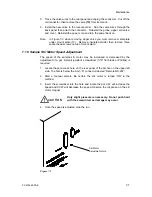
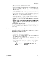
3. Blow through the lines with clean nitrogen or helium.
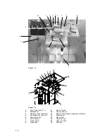
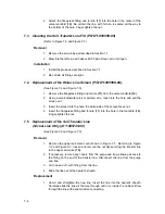
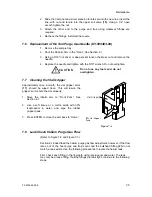
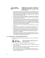
4. Remove the two lines (7or 8) from the bottom of the valve. These two lines
are water/sample supply lines to and from the valve manifolds. Unscrew the
lines from the manifold assemblies and using clean nitrogen or helium blow
through the lines.
5. Unscrew the knurled retaining knob (9) on the front of the valve body. Do not
use an Allen wrench.
6. With a small pick (the tool used to remove a GC septum works well) remove
the valve rotor. If this is not possible try a small magnet. Note the position of
the groove (loop) on the rotor. It MUST be facing down.
7. Blow through the valve (10) from the front using clean nitrogen or helium. Be
certain there is flow coming out of each hole.
8. Reattach all the lines to their proper locations. Be certain all the fittings are
tight.
9. Insert the rotor into the valve.
BE SURE THE GROOVE IS FACING DOWN!
Install the knurled knob. Using your fingers, tighten the knob until it will no
longer rotate.
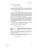
10. Turn the helium toggle switch to “ON.”
Note:
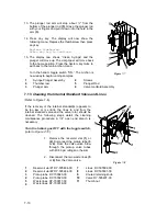
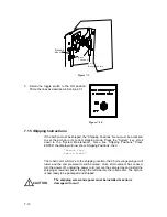
If it is necessary to remove the 5 ml standard reservoir vials, be very
certain the helium toggle switch is off. Grasp the vial before rotating the black
thumbnut (11).
7.14
Installation of the Internal Standard Vials
Before beginning a sample run, be certain the 5 ml Standard Vial(s) are filled with
the required internal standard or surrogate.
To fill the vials:
1. Turn the helium gas “OFF” with the toggle switch.
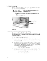
2. Grasp the vial and loosen the black thumbnut. Slide the vial with Thumbnut
and ferrule down clearing the pickup tube.
3. Clean the vial, dry it thoroughly and fill the vial with approximately 5 ml of
standard and / or surrogate.
4. Remove black thumbnut, slide over neck of vial with 3/8” Teflon ferrule (P/N
28-694637-00). Then slide the vial up into standard mount. Finger-tighten
until it is snug.
C A U T IO N
Do not use any tools and do not
overtighten.
Содержание archon
Страница 43: ...4 6 ...
Страница 73: ...6 18 ...
Страница 103: ...9 4 ...
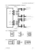
Страница 117: ...11 10 11 6 Interconnect Diagram Note F R L R and U D P O T should be set at 3 4 std valve full power ...
Страница 119: ...12 2 ...

