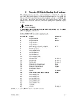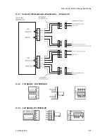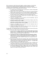
Remote I/O Cable Hookup Instructions
03-914642-00:6
8-7
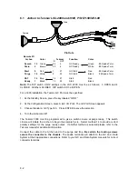
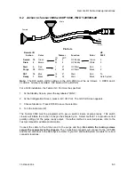
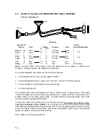
8.4
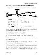
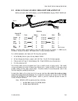
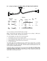
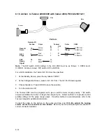
Archon to Tekmar LSC 2000 / 3000 with HP 5895/96/85/87/88/92
GC/MS with HP-1000/RTE GC/MS Software, HP 5890 MSD RTE (RTE-A, RTE-6, or Rev
F2), P/N DY-505876-00
Pin Outs
Remote I/O
Archon
Color
Tekmar
Function
Color
Connection
IN
OUT
Green
24
3
GC Ready
Red
25 / 27
Desorb
Drain
15
2
Brown
23
4 (Slave)
GC Ready
Black
26 / 28
Red
1
Start
Purge
5
18
White
2
Blue
16
21
GC/MS Remote Start Button
P&T
Ready
14
1
Black
15
22
(Master)
GC/MS Remote Start Button
Note: The DIP switch UO12 settings in the LSC 2000 must be as follows; 3 OPEN and 4
CLOSED. All others closed. DIP switch UO13 all open (If you are using the Master Cable or if
you are using Revision F or greater switch 5 is to be CLOSED.
For a 3000 installation, the Tekmar GC Port must be specified.
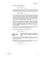
1. At the Standby Screen, press the key labeled “CONF.”
2. At the Configuration Screen, press A (GC I/O Port). The GC Port Screen appears.
3. Choose Standard. Press ENTER to save the selection. (Master mode) or user, GC Type=32
(slave mode).
4. Turn the instrument off.
The Tekmar 3000 must be programmed to give a switch closure at purge ready. This switch
closure will initiate the Archon to begin the sample Cycle. Select either method 14 or 15, to
provide correct polarity settings for the purge ready output. If another method is selected please
refer to the Tekmar manual for additional information.
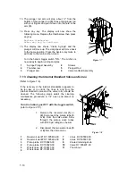
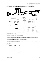
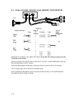
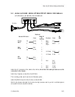
Connect the cable to the Archon and to the purge and trap. Be certain the locking screws
secure the connector to the chassis.
The Tekmar unit can be operated in one of two modes: Master mode or Slave mode. In Master
mode, the Tekmar unit commands or signals the GC/MS or data system to start processing a
Female
Male
Содержание archon
Страница 43: ...4 6 ...
Страница 73: ...6 18 ...
Страница 103: ...9 4 ...
Страница 117: ...11 10 11 6 Interconnect Diagram Note F R L R and U D P O T should be set at 3 4 std valve full power ...
Страница 119: ...12 2 ...

