Thermo Scientific 410iQ Скачать руководство пользователя страница 154

Operation 

Settings 

3-128

     410iQ Instruction Manual 

Thermo Scientific 


4.


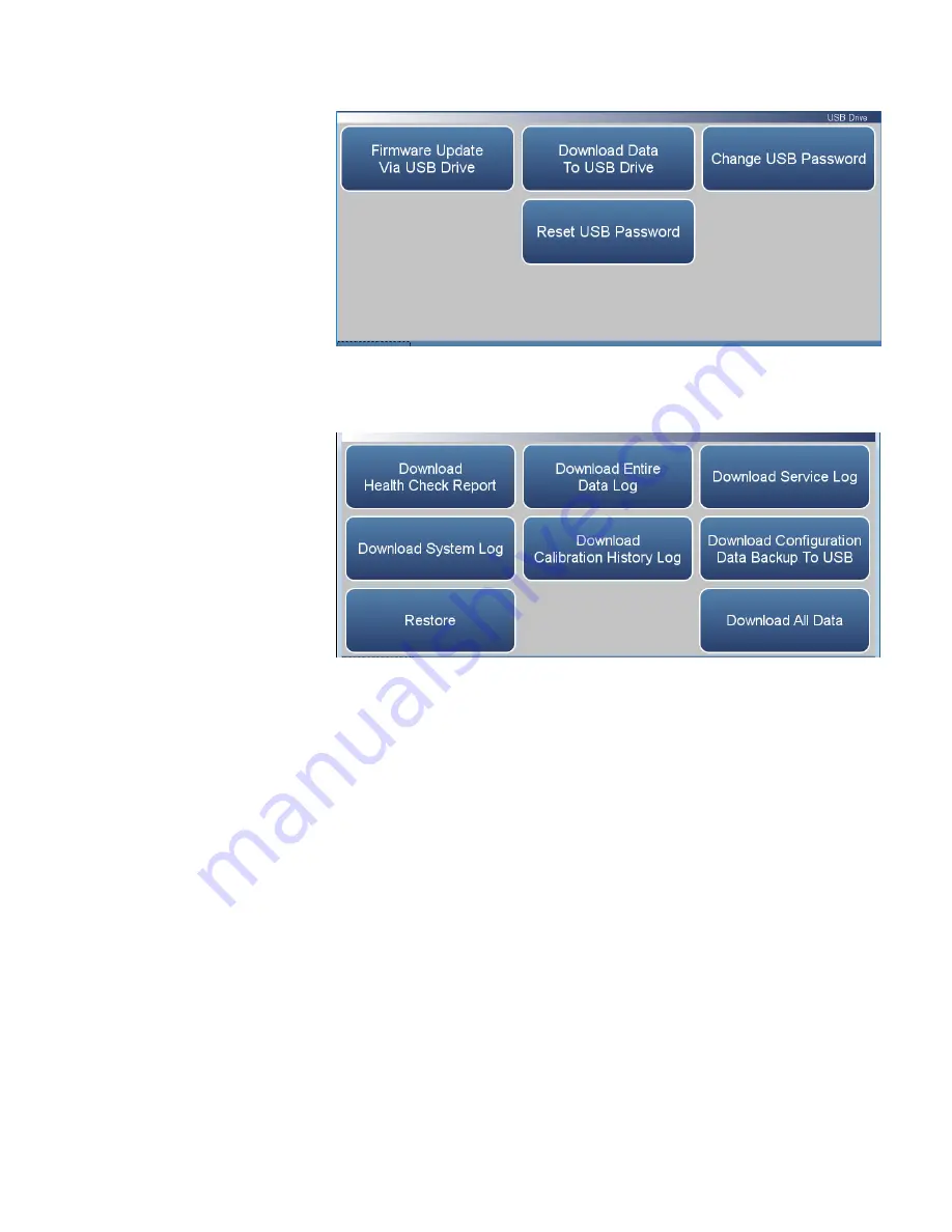
The Download Data to USB Drive screen will display. Select from 
various options to download. 


5.


The instrument will display a “downloading data” message and begin 
transferring data to the USB drive. 

Note  

Do not remove the USB drive from the instrument while the data 

is downloading


6.


When the data download is complete, the instrument will display a 
“Success!” message and display the file name as it is stored on the USB 
flash drive. (The file name format is the instrument serial number, 
name of download, followed by a date/time stamp.) Remove the USB 
flash drive and select the OK button to continue. 


Содержание 410iQ

Страница 1: ...410iQ Instruction Manual Carbon Dioxide Analyzer 117081 00 1Apr2020 ...

Страница 2: ......

Страница 3: ...3 1 Main Menus and Keypads 3 6 Numeric Keypad 3 7 Alphanumeric Keypad 3 8 Calibration 3 10 Calibrate Background 3 12 Calibrate Span Coefficient 3 13 Zero Span Schedule 3 15 Calibrate O2 Span Coefficient 3 17 Advanced Calibration 3 18 Manual Calibration 3 20 Multipoint Calibration 3 25 Manual O2 Calibration 3 28 2 Point O2 Calibration 3 30 Calibration History 3 32 Data 3 33 View Data Log Last Hour ...

Страница 4: ...ettings 3 73 Averaging Time 3 75 Range Mode Selection 3 77 Range Setting 3 79 Gas Mode 3 80 Gas Units 3 81 Advanced Measurement Settings 3 82 Communications 3 90 Wired TCP DHCP 3 92 Serial RS 232 485 3 94 Analog I O 3 95 Digital I O 3 96 Email Server SMTP 3 97 Bayern Hessen Settings 3 98 Ethernet Protocol Selection 3 99 Instrument Settings 3 100 Display Setup 3 101 Alarm Setpoints 3 102 Clock 3 10...

Страница 5: ...tion Frequency 4 8 Calibrate Background 4 9 Calibrate Span Coefficient 4 10 Periodic Zero and Span Checks 4 12 Manual Calibration 4 13 Adjust Background 4 13 Adjust Span Coefficient 4 14 Reset Bkg to 0 000 and Span Coef to 1 000 4 14 Zero Span Schedule 4 15 Next Time 4 15 Period 4 15 Zero Span Purge Duration Minutes 4 15 Schedule Averaging Time 4 16 Background Calibration and Span Calibration 4 16...

Страница 6: ... Replacement 7 28 DMC Optical Bench 7 31 Optical Bench Removal 7 33 Optical Switch Replacement 7 35 Purge Wheel Housing Removal 7 40 Filter Wheel Replacement 7 42 Motor Replacement 7 44 Motor and Filter Wheel Alignment 7 46 Optical Bench Heater Removal 7 48 Pre Amp Detector Assembly Removal 7 51 IR Source Replacement 7 54 Optional Manifold Replacement 7 57 Optional DMC Oxygen Sensor 7 59 Oxygen Se...

Страница 7: ...232 RS 485 Port 9 2 RS 485 External Accessory Port 9 3 Analog I O Board 9 4 Analog Voltage Inputs 9 4 Analog Voltage Outputs 9 5 Analog Output Calibration 9 6 Analog Output Zero Calibration 9 7 Analog Output Full Scale Calibration 9 9 Digital I O Board 9 11 Digital Inputs 9 11 Digital Relay Switches 9 13 Valve Driver Outputs 9 15 Internal Zero Span Assembly 9 17 Internal Oxygen O2 Sensor 9 18 PTFE...

Страница 8: ...Contents viii 410iQ Instruction Manual Thermo Scientific GNU Lesser General Public License C 1 GNU Lesser General Public License C 1 Appendix C ...

Страница 9: ...DMC module design simplifies serviceability Each DMC module contains its own microprocessor control enabling functional performance validation at the module level Built in predictive diagnostics and preventive maintenance schedules identify problems before they occur The iQ Series platform sends email notifications directly to Thermo Fisher Scientific s world class service support team or locally ...

Страница 10: ...ntific experience to simplify daily operations Custom designed ePort software allows remote access to the analyzer with a PC The ePort control mirrors the same GUI look and feel as the instrument touchscreen providing a speedy and familiar operational experience Figure 1 1 410iQ Front ...

Страница 11: ...igh Level Gas sample is drawn into the 410iQ through the rear panel of the analyzer and through the optical bench using an embedded intake pump as shown in Figure 1 2 Gas may be ambient or it may be delivered from a more distant location using standard tubing delivered to the rear panel The rear panel may be a simple inlet bulkhead or it could utilize three inlets controlled with solenoid valves C...

Страница 12: ...Introduction 410iQ Principle of Operation 1 4 410iQ Instruction Manual Thermo Scientific Figure 1 2 410iQ Flow Schematic Figure 1 3 410iQ Flow Schematic with Zero Span ...

Страница 13: ...e 1 0 SLPM 1 atm inlet pressure Operating Temperature Range 5 45 C may be safely operated over the range of 0 45 C Power Requirements 100 240 VAC 50 60 Hz 275 Watts Physical Dimensions 24 in D x 16 75 in W x 8 72 in H 609 mm D 425 45 mm W x 221 48 mm H Weight Standard 31 3 lbs High Level 30 1 lbs Analog I O 4 Isolated Voltage Inputs 0 10 V 6 Isolated Analog Voltages Outputs with 4 selectable range...

Страница 14: ...en Sensor Specifications Technology Paramagnetic Range 0 100 O2 Accuracy Intrinsic error 0 1 O2 Linearity 0 1 O2 Repeatability 0 1 O2 Zero Drift 0 2 O2 per month excludes up to 0 1 O2 in the first 24 hours of operation Response Time T10 T90 2 5 seconds Weight Approximately 2 lbs in addition to standard instrument ...

Страница 15: ...Introduction Dimensions Thermo Scientific 410iQ Instruction Manual 1 7 Figure 1 4 Bench Mount Assembly dimensions in inches mm Dimensions ...

Страница 16: ...Introduction Dimensions 1 8 410iQ Instruction Manual Thermo Scientific Figure 1 5 Rack Mount Assembly dimensions in inches mm ...

Страница 17: ...Introduction Dimensions Thermo Scientific 410iQ Instruction Manual 1 9 Figure 1 6 Rack Mount Requirements Figure 1 7 Rack Requirements Part 2 ...

Страница 18: ......

Страница 19: ...ng container when you receive the instrument notify the carrier immediately and hold for inspection The carrier is responsible for any damage incurred during shipment Use the following procedure to unpack and inspect the instrument 1 Remove the instrument from the shipping container and set it on a table or bench that allows easy access to both the front and rear 2 Remove the cover to expose the i...

Страница 20: ... the cover Equipment required Phillips screwdriver 2 1 Unfasten the four 8 32 screws securing the cover shipping screws 2 Press in both latches located on top cover and hold while pulling up to remove Set upright Figure 2 1 Removing the Cover 3 To replace align cover and drop in Latches will automatically snap in place Cover Removing and Replacing ...

Страница 21: ...trument can be installed in the following configurations Bench Mount Rack Mount Positioned on bench includes installing feet See Figure 2 2 Equipment required Slot drive 5 16 inch 1 Fasten feet in position 1 or 2 to fit to the desired depth Figure 2 2 Installing Feet Mounting Options Bench Mount ...

Страница 22: ...t required Phillips drive 2 1 Start by gripping from the top corners of the front panel and pull outwards Figure 2 3 Removing the Front Panel 2 Unfasten the four 8 32 pan head screws 3 Slide ears outwards 4 Use the same four 8 32 pan head screws to secure it 5 Install the handles with the four 8 32 flat head screws that came with the handle kit on the backside as shown Rack Mount ...

Страница 23: ...Installation and Setup Mounting Options Thermo Scientific 410iQ Instruction Manual 2 5 Figure 2 4 Installing Ears and Handles ...

Страница 24: ...re 2 6 if gas pressure is greater than atmospheric pressure 2 Connect the EXHAUST bulkhead to a suitable vent The exhaust line should be 1 4 inch OD with a minimum ID of 1 8 inch The length of the exhaust line should be less than 10 feet Verify that there is no restriction in this line 3 If the external purge filter is installed connect a source of pressurized clean dry zero air or a non toxic ine...

Страница 25: ... 2 7 6 Plug the instrument into an outlet of the appropriate voltage and frequency The 410iQ is supplied with a three wire grounding cord Under no circumstances should this grounding system be defeated Figure 2 5 410iQ Rear Panel Figure 2 6 Atmospheric Dump Bypass Plumbing Icon Here ...

Страница 26: ...e mode warm up is displayed on the gas mode button in the title bar and the concentration calculation is turned off To disable warm up go to Settings Configuration 4 Set instrument parameters such as operating ranges and averaging times to their appropriate settings For more information about instrument parameters see the Operation chapter 5 Before beginning the actual monitoring perform a multipo...

Страница 27: ... The User Interface located in the middle is where the Home Screen and all other screens are accessed The Home Screen has three Main Menu buttons located on the left side which include Calibration Data and Settings while the user interface to the right of the buttons displays the chemical name s concentration value s and unit s The Status Bar located at the bottom includes the Back button Access L...

Страница 28: ...y 3 2 410iQ Instruction Manual Thermo Scientific Home Screen 410iQ single range mode with O2 option Home Screen 410iQ dual or auto range mode with O2 option Title Bar User Interface Status Bar Title Bar User Interface Status Bar ...

Страница 29: ...Thermo Scientific 410iQ Instruction Manual 3 3 Home Screen 410iQHL single range mode with O2 option Home Screen 410iQHL dual or auto range mode with O2 option Title Bar User Interface Status Bar Title Bar User Interface Status Bar ...

Страница 30: ...al time status and alarms also predictive diagnostics and maintenance history Contains controls for operating the instrument communications and sets instrument options Concentration When in single mode displays CO2 concentrations in big bold characters depending on operating mode When in dual or auto mode displays either high range or low range values based on the range setting Status Bar Back but...

Страница 31: ...Operation Instrument Display Thermo Scientific 410iQ Instruction Manual 3 5 Thermo Scientific Information button Shows contact information ...

Страница 32: ...ging Time Range Mode Selection Range Setting Gas Mode Gas Units Dilution Ratio Advanced Measurement Optical Bench Settings Compensation Pressure Calibration Instrument Settings Display Setup Alarm Setpoints Language Clock Pump Power Reboot Instrument Communications Configuration Security Access Levels USB Drive Firmware Update Via USB Drive Download Data to USB Drive Change USB Password User Conta...

Страница 33: ...uch as for flow rates temperatures or pressures the keypad screen will automatically display Initially the box above the keypad will display the current value Enter a new value using the keypad and then select the Enter button to set the new value or press the Cancel button to exit the keypad screen and return to the previous screen without saving the value Numeric Keypad ...

Страница 34: ...utomatically display Initially the box above the keypad will display the current value Enter a new value using the keypad and then select the Enter button to set the new value or press the Cancel button to exit the keypad screen and return to the previous screen without saving the value The alphanumeric keypad is only available when the user needs to enter alphabet characters Alphanumeric Keypad ...

Страница 35: ...Operation Instrument Display Thermo Scientific 410iQ Instruction Manual 3 9 ...

Страница 36: ...nd auto range modes have two CO2 span factors high and low This allows each range to be calibrated separately This is necessary if the two ranges used are not close to one another For example a low CO2 range of 200 ppm and a high CO2 range of 1000 ppm For more information about range modes see Range Mode Selection on page 3 77 Home Screen Calibration single range mode with O2 option Home Screen Ca...

Страница 37: ...en in dual or auto range mode Zero Span Schedule Programs the instrument to perform fully automated zero and span checks or adjustments Calibrate O2 Span Coefficient When the O2 Sensor option is turned on in the Settings Configuration screen this button will appear It allows an O2 calibration to be performed Advanced Calibration Calibrates the instrument using a standard zero span calibration a mu...

Страница 38: ... stabilize each time input gas is changed and set the averaging time to 300 second averaging Home Screen Calibration Calibrate Background The Calibrate Background menu contains the following information Target Concentration Read only Displays what the concentration value will become when the calibrate button is pressed Current Background Read only Displays what the current user set background is C...

Страница 39: ...e the calibration of the high or low coefficient The Calibrate High Range Span Coefficient and Calibrate Low Range Span Coefficient screens function the same way It is important to note the averaging time when calibrating The longer the averaging time the more precise the calibration results To achieve maximum precision allow the instrument to stabilize each time input gas is changed and set the a...

Страница 40: ... is when in single range mode Current High Range Span Coefficient Displays what the current user set high range span coefficient is when in dual or auto range mode Current Low Range Span Coefficient Displays what the current user set low range span coefficient is when in dual or auto range mode Calculated Span Coefficient Read only After the Edit Span Concentration value is entered the new calcula...

Страница 41: ...ation Zero Span Schedule Toggles zero span schedule Enabled or Disabled Next Time Allows the user to view and set the initial date and time 24 hour format of the zero span schedule Period Defines the period or interval between zero span checks or calibrations If period 0 the schedule runs continuously Zero Duration Sets how long zero air is sampled by the instrument Span Duration Sets how long spa...

Страница 42: ...uns a background check only and background value is not updated Span Calibration Toggles Enabled Disabled If enabled span coefficient is calibrated If disabled schedule runs a calibration check only and span coefficient is not updated Zero Span Ratio Allows the user to perform more scheduled background calibration checks to span calibration checks Default is 1 and therefore reads 1 1 This means th...

Страница 43: ...averaging time to 300 second averaging The O2 Averaging Time is located at Settings Measurement Settings Averaging Time Home Screen Calibration Calibrate O2 Span Coefficient single range mode The Calibrate O2 Span Coefficients screen contains the following information Edit O2 Span Concentration User enters the O2 span concentration Current O2 Concentration Read only Current O2 concentration readin...

Страница 44: ...etween the screens are the words High Range and Low Range For more information about range modes see Range Mode Selection on page 3 77 Home Screen Calibration Advanced Calibration single range mode Home Screen Calibration Advanced Calibration dual or auto range mode The Advanced Calibration screens contain the following information Manual Calibration The user manually adjusts the background or spa...

Страница 45: ... Range Multipoint Calibration Up to three gas concentrations cal points for low range may be calibrated Three cal points will give the most accurate readings over the entire range Manual O2 Calibration The user manually adjusts the O2 span coefficient based on the current O2 concentration value 2 Point O2 Calibration The user manually performs a 2 point calibration of the O2 sensor Calibration His...

Страница 46: ... In dual or auto range modes High Range or Low Range buttons are displayed to indicate the calibration of the high or low coefficient Home Screen Calibration Advanced Calibration Manual Calibration single range mode Home Screen Calibration Advanced Calibration Manual Calibration dual or auto range mode The Manual Calibration menu contains the following information Adjust Background Allows the user...

Страница 47: ... user to manually adjust the high range span coefficient when in dual or auto range mode Adjust Low Range Span Coefficient Allows the user to manually adjust the low range span coefficient when in dual or auto range mode Reset Background to 0 000 and Span Coefficient to 1 000 Resets all backgrounds and coefficients ...

Страница 48: ...nced Calibration Manual Calibration Adjust Background The Adjust Background screen contains the following information Adjust Background User manually adjusts zero background Adjusted Concentration Read only Shows adjusted concentration based on adjusted zero background Calibrate Calibrates zero background by saving the newly adjusted zero background value Adjust Background ...

Страница 49: ... Span Coefficient and Adjust Low Range Span Coefficient screens function the same way Home Screen Calibration Advanced Manual Calibration Adjust Span Coefficient single range mode Home Screen Calibration Advanced Manual Calibration Adjust High Range Span Coefficient dual or auto range mode The Adjust Span Coefficient menu contains the following information Adjust Span Coefficient User manually adj...

Страница 50: ...tion based on adjusted span coefficient Adjusted High Range Concentration Read only Shows adjusted high range concentration based on adjusted high range span coefficient when in dual or auto range mode Adjusted Low Range Concentration Read only Shows adjusted low range concentration based on adjusted low range span coefficient when in dual or auto range mode Calibrate Calibrates span coefficient b...

Страница 51: ...Calibration screens function the same way Note Pressing the Multipoint Calibration button responds with It is recommended to calibrate all three points and requires and OK action Home Screen Calibration Advanced Calibration Multipoint Calibration single range mode The Multipoint Calibration screen contains the following information Point 1 First cal point used in the calibrated multipoint polynomi...

Страница 52: ...ration 3 26 410iQ Instruction Manual Thermo Scientific Third Coefficient Read only Value of the third coefficient in the polynomial curve Reset Points to Default Values Resets multipoint coefficients to default values ...

Страница 53: ...tion screens function the same way The customer defines the ranges It is suggested to perform the following calibration points for each range Cal point 1 80 of range Cal point 2 50 or range Cal point 3 20 of range Home Screen Calibration Advanced Calibration Multipoint Calibration Point 1 The Point 1 screen contains the following information Edit Point 1 Span Concentration User enters span concent...

Страница 54: ...tration This button appears if the O2 Sensor option is selected in the Configuration screen Home Screen Calibration Advanced Calibration Manual Calibration single range mode The Manual O2 Calibration screen contains the following information Adjust O2 Span Coefficient Allows the user to manually adjust the O2 span coefficient Reset O2 Coefficient to 1 000 Resets coefficient Manual O2 Calibration ...

Страница 55: ...ual Calibration Adjust O2 Span Coefficient The Adjust O2 Span Coefficient menu contains the following information Adjust O2 Span Coefficient User manually adjusts span coefficient Adjusted Concentration Read only Shows adjusted O2 concentration based on adjusted O2 span coefficient Calibrate Calibrates span coefficient by saving the newly adjusted O2 span coefficient Adjust O2 Span Coefficient ...

Страница 56: ...n appears if the O2 Sensor option is selected in the Configuration screen Home Screen Calibration Advanced Calibration 2 Point O2 Calibration Home Screen Calibration Advanced Calibration 2 Point O2 Calibration Continue to 2 Point O2 Calibration The 2 Point O2 Calibration screen contains the following information 2 Point O2 Calibration Point 1 First cal point used in the 2 point O2 calibration Defa...

Страница 57: ...int O2 Calibration 2 Point O2 Calibration Point 1 The 2 Point O2 Calibration Point 1 screen contains the following information Edit O2 Span Concentration User enters O2 span concentration Current O2 Concentration Read only After selecting the value on the Edit O2 Concentration button and after pressing the Calibrate O2 button the Point 1 Concentration value is updated Calibrate O2 Point 1 Calibrat...

Страница 58: ... Calibration History Note Pressing the Calibration History button responds with Retrieving calibration log data it may take a few seconds The Calibration History screen contains the following information Time Stamp Time of calibration or calibration check Event Lists the type of calibration event Result Concentration result Target Concentration setpoint value Units Displays units for each item Ave...

Страница 59: ...ollowing information View Data Log Last Hour User views last hour of historical data Table shows most recent data on top View Data Log Last 24 Hours User views 24 hour of historical data Table shows most recent data on top View Data Log User Defined Time User selects the start and end time for viewing the data Table shows most recent data on top Advanced Data Setup Allows the user to set up the pa...

Страница 60: ...up and down and the and buttons to move left and right Home Screen Data View Data Log Last Hour Note Pressing the View Data Log Last Hour responds with Retrieving user log data it may take a few seconds The View Data Log Last Hour screen contains the following options Graph Displays data graph for the column selected The graph time axis is defined by the data set in the table View Data Log Last Ho...

Страница 61: ...nd down and the and buttons to move left and right Home Screen Data View Data Log Last 24 Hours Note Pressing the View Data Log Last 24 Hours responds with Retrieving user log data it may take a few seconds The View Data Log Last 24 Hours screen contains the following options Graph Displays data graph for the column selected The graph time axis is defined by the data set in the table View Data Log...

Страница 62: ... Time Home Screen Data View Data Log User Defined Time Save Data Logging Start Time The View Data Log User Defined Time screen contains the following information Date Sets date of data logging start time Time Sets time of data logging start time Save Data Logging Start Time Pressing this button saves the start time and follows directly to the end time selection for the data logging screen View Dat...

Страница 63: ...mation Date Sets date of data logging end time Time Sets time of data logging end time Save Data Logging End Time Pressing the Save Data Logging End Time button saves the end time and follows directly to the data logging table Note End time should not be greater than 1 year from start time Note The datalogging table is limited to 10 000 points ...

Страница 64: ...t up parameters for data logging and streaming data Home Screen Data Advanced Data Setup The Advanced Data Setup screen contains the following information Data Logging Setup User selects the parameters for collecting logged data Streaming Data Setup User selects the parameters for streaming data to a computer in real time Advanced Data ...

Страница 65: ...ariables to log Period User selects how often data is collected by setting the duration between logged data Data Treatment Toggles between Average Current Minimum and Maximum When set to average the average value during the period will be recorded When set to current the latest data will be recorded When set to minimum or maximum the minimum or maximum value during the period will be recorded Eras...

Страница 66: ... other but contain the same variable selections The list is based on the instrument s configuration Use the and buttons to scroll through the variables Select the variables to log by pressing the corresponding cells Next press the Commit Changes button to save selections Yellow buttons indicate that the variable is selected Home Screen Data Advanced Data Logging Setup Select Data Logging Variables...

Страница 67: ...tup The Streaming Data Setup screen contains the following information Select Streaming Variables User selects which variables to stream Period Sets the time between streamed data Show Labels Toggles on off When on shows variable labels to the left of the variable values Show Timestamp Toggles on off When on shows timestamp at the beginning of each row of data Streaming Data Setup ...

Страница 68: ...h other but contain the same variable selections The list is based on the instrument s configuration Use the and buttons to scroll through the variables Select the variables to log by pressing the corresponding cells Next press the Commit Changes button to save selections Yellow buttons indicate that the variable is selected Home Screen Data Advanced Streaming Data Setup Select Streaming Variables...

Страница 69: ...ct Thermo Fisher Scientific technical support Measurement Settings Allows the user to setup user preferences as related to the concentration readings Communications Allows the user to communicate with outside devices Instrument Setting Allows the user to setup alarm setpoints and user preferences Configuration User selects which options to enable Security Access Levels User selects security protoc...

Страница 70: ... following information Status and Alarms Allows the user to view the status and alarm menus Menus are broken down according to modules where the user can view instrument readings setpoints and alarms Predictive Diagnostics Smart module diagnostics which shows possible future issues Maintenance History Allows the user to set up a maintenance schedule and track maintenance history File Sharing and S...

Страница 71: ...en Settings Health Check Status and Alarms The Status and Alarms menu contains the following information Concentration Displays CO2 concentrations and alarms NDIR Bench Displays bench module alarms and faults O2 Sensor Displays O2 concentrations sensor alarms and faults if enabled Flow and Pressure Displays flow and pressure alarms and faults Peripherals Support Displays peripherals support alarms...

Страница 72: ...centration The Concentration screen contains the following information Across Concentration This column lists items associated with the CO2 concentrations Value Displays the current value for each item Low Alarm Displays low alarm status for each item High Alarm Displays high alarm status for each item Span Conc Span concentration used in the span calibration or span check Units Displays units for...

Страница 73: ...ys concentration based on the last attempted span calibration High alarm shows user defined limit for acceptable span check offset compared to the span concentration value Span concentration shows span setpoint Note If both the low alarm and high alarms are set to zero then no alarm will show ...

Страница 74: ... Across NDIR Bench This column lists items associated with the NDIR bench module Value Displays the current value for each item Low Alarm Displays low alarm status for each item High Alarm Displays high alarm status for each item Units Displays units for each item Down S R Displays the current sample reference reading Sample Intensity Displays the current sample intensity reading Reference Intensi...

Страница 75: ...tor Bias too High Displays OK Fail for IR detector bias too high Bench Thermistor Open Displays OK Fail for bench thermistor open Bench Thermistor Short Displays OK Fail for bench thermistor short Module Thermistor Open Displays OK Fail for module thermistor open Module Thermistor Short Displays OK Fail for module thermistor short Board Communication Displays OK Fail for board communication status...

Страница 76: ...ttings 3 50 410iQ Instruction Manual Thermo Scientific 15V Diagnostic Displays current voltage readings Alarm limits are not changeable Bias Voltage Displays current voltage readings Alarm limits are not changeable ...

Страница 77: ... lists items associated with the O2 sensor Value Displays the current value for each item Low Alarm Displays low alarm status for each item High Alarm Displays high alarm status for each item Units Displays units for each item Down Concentration Displays the current O2 sensor concentration reading User can adjust low and high alarm limits Temperature Displays the current temperature reading Temper...

Страница 78: ...cation Displays OK Fail for board communication status Power Supply Displays OK Fail of power supplies Power supply goes red if any voltages are outside their limits No voltage rows ever get highlighted 2 5V Diagnostic Displays current voltage readings Alarm limits are not changeable 3 3V Diagnostic Displays current voltage readings Alarm limits are not changeable 5 0V Diagnostic Displays current ...

Страница 79: ...ation Across Flow and Pressure This column lists items associated with the flow and pressure module Value Displays the current value for each item Low Alarm Displays low alarm status for each item High Alarm Displays high alarm status for each item Units Displays units for each item Down Flow Displays the current sample flow reading User can adjust low and high alarm limits Bench Pressure Displays...

Страница 80: ... if any voltages are outside their limits No voltage rows ever get highlighted 2 5V Diagnostic Displays current voltage readings Alarm limits are not changeable 3 3V Diagnostic Displays current voltage readings Alarm limits are not changeable 5 0V Diagnostic Displays current voltage readings Alarm limits are not changeable 24V Diagnostic Displays current voltage readings Alarm limits are not chang...

Страница 81: ...n Across Peripherals Support This column lists items associated with the peripherals support module Value Displays the current value for each item Low Alarm Displays low alarm status for each item High Alarm Displays high alarm status for each item Units Displays units for each item Down Module Temperature Displays the current module temperature of the module Sample Valve Displays whether or not t...

Страница 82: ...ir limits No voltage rows ever get highlighted 2 5V Diagnostic Displays current voltage readings Alarm limits are not changeable 3 3V Diagnostic Displays current voltage readings Alarm limits are not changeable 5 0V Diagnostic Displays current voltage readings Alarm limits are not changeable 24V Diagnostic Displays current voltage readings Alarm limits are not changeable 5 0V Step Board Displays O...

Страница 83: ...s symbol denotes that the device needs to be reset Note Resetting one valve will reset all valves Home Screen Settings Health Check Status and Alarms Valve and Pump Resets The Valve and Pump Resets screen contains the following information Sample Valve Reset Resets sample valve Zero Valve Reset Resets zero valve Span Valve Reset Resets span valve Pump Reset Resets pump Valve and Pump Resets ...

Страница 84: ...ntains the following information Across Analog IO This column lists items associated with the analog I O Value Displays the current value for each item Low Alarm Displays low alarm status for each item High Alarm Displays high alarm status for each item Units Displays units for each item Down Voltage Output Channel 1 6 Displays real time voltage output for each channel Current Output Channel 1 6 D...

Страница 85: ...No voltage rows ever get highlighted 3 3V Diagnostic Displays current voltage readings Alarm limits are not changeable 5 0V Diagnostic Displays current voltage readings Alarm limits are not changeable 5 0V Ref Diagnostic Displays current voltage readings Alarm limits are not changeable 15V Diagnostic Displays current voltage readings Alarm limits are not changeable 15V Diagnostic Displays current ...

Страница 86: ...he following information Across Digital IO This column lists items associated with the digital I O Value Displays the current value for each item Reset Resets item Low Alarm Displays low alarm status for each item High Alarm Displays high alarm status for each item Units Displays units for each item Down Solenoid 1 8 Displays whether or not the solenoid is activated by showing the current in mA Ex...

Страница 87: ...oes red if any voltages are outside their limits No voltage rows ever get highlighted 3 3V Diagnostic Displays current voltage readings Alarm limits are not changeable 5 0V Diagnostic Displays current voltage readings Alarm limits are not changeable 24V Diagnostic Displays current voltage readings Alarm limits are not changeable ...

Страница 88: ...The Serial Numbers screen contains the following information Instrument Instrument serial number NDIR Bench NDIR bench serial number O2 Sensor Board O2 sensor board serial number O2 Sensor O2 sensor serial number Flow and Pressure Flow and pressure serial number Peripherals Support Peripherals support serial number Analog I O Analog I O serial number Digital I O Digital I O serial number Serial Nu...

Страница 89: ... button is greyed out no maintenance is needed If button is blue maintenance is suggested Note This symbol denotes there is an active maintenance related warning in the module Home Screen Settings Health Check Predictive Diagnostics The Predictive Diagnostics screen contains the following information Filter Wheel Sample Pump Capillary Flow Path IR Source Sample Valve Zero Valve Span Valve Predicti...

Страница 90: ...s Health Check Maintenance Home Screen Settings Health Check Maintenance Advanced Maintenance The Maintenance screen contains the following information Preventive Maintenance Shows suggested service interval and time left for component replacement Change Part User logs component fix Maintenance History Shows the log of all recorded component fixes Service Tips Provides video and procedural service...

Страница 91: ...e Preventive Maintenance screen contains the following information Across Component Device to be routinely serviced or replaced Interval in Months Expected period of time before a component needs to be checked and or serviced User settable Months Left Count down timer in months Remaining time since the beginning of the service interval When the value is 1 or less the row will be highlighted and it...

Страница 92: ...Service interval for chopper motor Optical Switch Service interval for optical switch Flow System Service interval for the flow system components Capillaries Service interval for capillaries Pump Service interval for pump DC Power Supply Service interval for DC power supply Fan Filter Service interval for fan filter System Components Service interval for system components Purafil Service interval ...

Страница 93: ...e diagnostics screen when applicable Home Screen Settings Health Check Maintenance Change Part The Change Part screen contains the following information Select Part User selects part to service from the selection table Fix User chooses from new rebuilt cleaned and unknown Comment User can write a brief comment which will be saved to the preventive maintenance history table Commit User commits and ...

Страница 94: ...nd down and the and buttons to move left and right Home Screen Settings Health Check Maintenance Maintenance History Note Pressing the Maintenance History button responds with Retrieving maintenance history data it may take a few seconds The Maintenance History screen contains the following information Part Component that has been fixed Fix The type of maintenance Date Shows date time when service...

Страница 95: ...rive Email Health Check Report File to Technical Support Sends the health report file to technical support and the customer email addresses via email Email Health Check Report to Personal Account Sends the health report file to a personal account via email iQ Alert Assistant With the iQ Alert Assistant enabled the instrument will email Thermo Scientific Technical Support the health check report af...

Страница 96: ...ngs Health Check iQ360 Get Started Home Screen Settings Health Check iQ360 Status and Renewal Request The iQ360 screen contains the following information Get Started Allows the user to access the menu where the subscription passcode is entered Status and Renewal Request Allows the user to access the iQ360 menu once the subscription has been enabled Cancel and Return to the Home Screen Exits screen...

Страница 97: ...eck iQ360 Get Started The Get Started screen contains the following information Resend Subscription E mail Allows the user to request another subscription passcode if the email was never received Enter Subscription Access Code Allows the user to enter the subscription passcode to enable an iQ360 subscription Exit and Return to the Home Screen Exits screen and returns to the Home Screen Get Started...

Страница 98: ...nd Renewal Request The Status and Renewal Request screen contains the following information iQ360 Status Informs the user if the subscription is enabled iQ360 Subscription Expiration Date Informs the user when the subscription will expire iQ360 Test Connection Allows the user to verify the network connection is working iQ360 Subscription Renewal Allows the user to request a subscription renewal vi...

Страница 99: ... will be available Home Screen Settings Measurement Settings single range mode Home Screen Settings Measurement Settings dual or auto range mode The Measurement Setting menu contains the following information Averaging Time Sets the averaging time for the CO2 sample measurement and O2 sample measurement if option is enabled Range Mode Selection User can choose between the various range modes singl...

Страница 100: ...e Low Range Setting Sets the low range concentration for the analog output when in dual or auto range mode Gas Mode User can manually choose sample zero or span mode Gas Units Defines the units in which CO2 concentration reading is expressed Dilution Ratio Serves as a multiplier when dilution gas is utilized Advanced Measurement Settings Advanced settings affecting CO2 readings ...

Страница 101: ...00 seconds will be the output at each update Therefore the lower the averaging time the faster the front panel display and analog outputs respond to concentration changes Longer averaging times are typically used to smooth output data Dynamic Filtering allows for data smoothing without compromising response time Automatically changes the averaging time giving the user faster response times when co...

Страница 102: ...amic filtering when in dual or auto range mode Low Range Dynamic Filtering Enables disables low range dynamic filtering when in dual or auto range mode Averaging Time Sets averaging time period in single range mode and when dynamic filtering is disabled High Range Averaging Time Sets high averaging time when in dual or auto range mode and when dynamic filtering is disabled Low Range Averaging Time...

Страница 103: ...ut can be set to output concentrations from 0 to 500 ppm and the high CO2 analog output set to output concentrations from 0 to 1000 ppm In addition each CO2 analog output has a span coefficient so that each range can be calibrated separately This is especially necessary if the two ranges are not close to one another For example the low CO2 range is set to 0 200 ppm and the high CO2 range is set to...

Страница 104: ...re than 1 order of magnitude For instance if the low range is set to 200 ppm then the high range should be set to no more than 2000 ppm This is because the concentration response is non linear and it is possible that the low range readings could become unpredictable above the top of the low range resulting in a substantial jump in concentration readings when switching between ranges One possible f...

Страница 105: ... only difference between the screens are the words High or Low displayed to indicate which range is displayed For more information about the dual and auto range modes see Range Mode Selection on page 3 77 Pressing Range Setting High Range Setting or Low Range Setting brings up a numeric keypad whereby the user can select a range Settable ranges according to unit selection include ppb 200 000 10 00...

Страница 106: ...ttings Measurement Settings Gas Mode The Gas Mode screen contains the following information Sample Sets the instrument to measure sample gas Zero Used when calibrating the background of the instrument When pressed sets the instrument to zero mode Span Used when calibrating the span coefficient When pressed sets the instrument to span mode Gas Mode ...

Страница 107: ... standard pressure of 760 mmHg and a standard temperature of 0 C The temperature can be changed in the compensation screen Use the and buttons to select Home Screen Settings Measurement Settings Gas Units The Gas Units screen contains the following information ppb parts per billion ppm parts per million percent μg m3 micrograms per meter cubed mg m3 milligrams per meter cubed g m3 grams per meter ...

Страница 108: ...nt Settings Advanced Measurement Settings The Advanced Measurements Settings menu contains the following information Optical Bench Settings User sets the detector gain and S R initial value This can be done manually or automatically Compensation Allows the user to compensate for changes in temperature pressure and oxygen concentration if enabled Pressure Calibration Calibrates pressure Advanced Me...

Страница 109: ...e and buttons to move up and down and the and buttons to move left and right Home Screen Settings Measurement Settings Advanced Measurement Settings Optical Bench Settings Home Screen Settings Measurement Settings Advanced Measurement Settings Optical Bench Settings Continue to Detector Gain Calibration The Detector Gain Calibration screen contains the following information Across Description Defi...

Страница 110: ...he Stop button End Cal When Stop is pressed the auto calibration is interrupted and the value does not change Default Values When pressed the default gain value is saved Home Screen Settings Measurement Settings Advanced Measurement Settings Optical Bench Settings Continue to Initial S R Calibration The Initial S R Calibration screen contains the following information Across Description Defines th...

Страница 111: ... the auto calibration process is initiated Please allow up to 5 minutes for calibration to complete User can Stop calibration by pressing the Stop button End Cal When pressed the auto calibration is interrupted and the value does not change Default Values When pressed the default S R value is saved ...

Страница 112: ... internal instrument temperature changes on the analyzer s subsystems and output have been empirically determined This empirical data is used to compensate for any changes in temperature Pressure Compensation Toggles pressure compensation enabled or disabled and provides compensation for any changes to the instrument s output signal due to bench pressure variations The effects of bench pressure ch...

Страница 113: ... non corrected values 2 9 20 2 9 20 2 O O C O C meas corr corr comp Abbreviations C is the measured concentration O2corr is the oxygen concentration that C is corrected to this value is set by the user in the Source O2 Concentration Setpoint screen and defaults to 15 O2meas is the measured O2 concentration which is clamped at 20 8 to prevent divide by zero errors Ccomp is the corrected concentrati...

Страница 114: ...tpoint User enters expected O2 concentration Current O2 Concentration Read only Displays current O2 reading Corrected CO2 Concentration Read only Displays the corrected CO2 concentration when in single range mode Corrected High Range CO2 Concentration Read only Displays the corrected high range CO2 concentration when in dual or auto range mode Corrected Low Range CO2 Concentration Read only Displa...

Страница 115: ...sor Calibration Starts calibration or resets default values Down Sensor 1 3 Reading Under the column labeled Reading current reading of each pressure sensor Atmospheric Sensor 1 3 Under the column labeled reading the user enters the current atmospheric pressure in mmHg units Under the column labelled Calibration the user presses the Start button to calibrate the high point of the sensor Zero Senso...

Страница 116: ...ation Communications Board Analog I O Settings for communicating with the instrument through analog I O settings This is only visible if selected in Settings Configuration Analog I O Digital I O Settings for communicating with the instrument through digital I O settings This is only visible if selected in Settings Configuration Digital I O Email Server SMTP Settings for communication with email In...

Страница 117: ...t the instrument should respond with in response to a valid data query DA command Note Refer to the Bayern Hessen Protocol section in the Communications Manual for a detailed description Ethernet Protocol Selection Allows the user to enable Streaming Modbus or Bayern Hessen to utilize the mobile app and or those communication protocols ...

Страница 118: ...Screen Settings Communications Wired TCP DHCP with DHCP enabled Home Screen Settings Communications Wired TCP DHCP with DHCP disabled The Wired TCP DHCP screen contains the following information DHCP Toggles DHCP enabled disabled Dynamic IP Address Dynamic IP address of the instrument Dynamic Netmask Dynamic Netmask of instrument Dynamic Gateway Dynamic Gateway of instrument Static IP Address Stat...

Страница 119: ... of instrument This is settable when DHCP is disabled Static Gateway Static Gateway of instrument This is settable when DHCP is disabled DNS Server Address DNS IP address of instrument This is settable when DHCP is disabled Wired MAC Address Instrument MAC address Host Name Host name of instrument ...

Страница 120: ...e Screen Settings Communications Serial RS 232 485 The Serial RS 232 485 screen contains the following information Protocol User selects Streaming Modbus or Bayern Hessen Baud Rate User selectable baud rates from 1200 to 115200 Bits User selectable between 7 and 8 Parity User selectable between None Even and Odd Stop Bits User selectable between 1 and 2 RS 232 485 User selectable between RS 232 an...

Страница 121: ... Analog In Allows the user to view and calibrate voltage inputs from external devices Analog Out Voltage Allows the user to view voltage outputs Analog Out Current Allows the user to view current mA outputs Analog Out Under Over Range Enabled Disabled Allows the user to select whether or not the analog outputs are allowed to exceed the selected output range Analog Out Calibration Allows the user t...

Страница 122: ... Digital I O Home Screen Settings Communications Digital I O The Digital I O screen contains the following information Digital In Allows the user to view digital inputs from external devices Digital Out Relays Allows the user to view relay outputs Digital Out Solenoids Allows the user to view solenoid outputs Advanced Digital I O Allows user to test the digital out relays and solenoids Digital I O...

Страница 123: ...Server SMTP The Email Server SMTP screen contains the following information SMTP Server Address Address of the user s email server From Email Address The email address that goes in the From field in emails SMTP Server Port Server port of user s email server Email Password Password for SMTP server Email UserName User name that is authorized to send email through SMTP server Email Server SMTP ...

Страница 124: ...tings The Bayern Hessen Settings screen contains the following information Across Number Lists up to 8 registers that can selected by the user Register User selects the measured values to be logged Meter Number Allows the user to choose the meter register number 001 to 999 that will preface the measured value in the response to the DA command Down 1 8 Displays the register number and the measured ...

Страница 125: ...ilize the mobile app and or those communication protocols Press Commit changes button to save selections Yellow buttons indicate that the selection is enabled More than one can be chosen Home Screen Settings Communications Ethernet Protocol Selection The Ethernet Protocol Selection screen contains the following information Streaming Modbus Bayern Hessen Ethernet Protocol Selection ...

Страница 126: ...ttings Instrument Settings The Instrument Settings screen contains the following information Display Setup Sets touch screen display settings Alarm Setpoints View and set all available alarm minimum and maximum values Language Sets language Clock Sets date and time Pump Power Manually enables disables the pump Reboot Instrument Reboots the instrument Instrument Settings ...

Страница 127: ...er save option Home Screen Settings Instrument Settings Display Setup The Display Setup screen contains the following information Power Save Minutes before screen times out Toggles enable disable Power Save Setting Option whereby the user can display a black screen after a set amount of inactivity Brightness Sets the brightness of the display Display Setup ...

Страница 128: ...screen See Status and Alarms on page 3 45 Use the and buttons to move up and down and the and buttons to move left and right Home Screen Settings Instrument Settings Alarm Setpoints The Alarm Setpoints screen contains the following information Across Item Lists the items that have settable alarm limits Value Displays the current value for each item Low Alarm User sets low alarm for item High Alarm...

Страница 129: ...r can set the maximum allowable span reading offset for calibration and calibration checks This is set with the high alarm only Instrument Temperature Instrument temperature alarm Bench Pressure Bench pressure alarm Flow Flow pressure alarm O2 concentration O2 concentration alarm if enabled ...

Страница 130: ...ion Manual Thermo Scientific The Language screen allows the user to choose from the following languages Home Screen Settings Instrument Settings Language The Language screen contains the following information English Chinese Spanish Language ...

Страница 131: ...ime zone and time server Home Screen Settings Instrument Settings Clock The Clock screen contains the following information Date User sets date Date Format User selects date format Time User sets time Time Zone User chooses time zone Time Server User can enable disable the time server to get periodic clock updates Commit When pressed clock settings are saved Clock ...

Страница 132: ...3 106 410iQ Instruction Manual Thermo Scientific The Date screen allows the user to choose date Use the and buttons to move left and right to select month and year Home Screen Settings Instrument Settings Clock Date Date ...

Страница 133: ... the user to choose from the following formats mm dd yyyy or dd mm yyyy Use the and buttons to select Home Screen Settings Instrument Settings Clock Date Format The Date Format screen contains the following information U S Format mm dd yyyy European Format dd mm yyyy ISO 8601 yyyy mm dd Date Format ...

Страница 134: ...entific The Time screen allows the user to choose from the following formats mm dd yyyy or dd mm yyyy Use the and buttons to select Home Screen Settings Instrument Settings Clock Time The Time screen contains the following information Hours Minutes Seconds Time ...

Страница 135: ...ent Settings Clock Time Zone The Time Zone screen contains the following information Date Line West UTC 12 Samoa Time Zone UTC 11 Aleutian Time Zone UTC 10 Alaskan Time Zone UTC 9 Pacific Time Zone UTC 8 Pacific Daylight Savings UTC 7 Mountain Time Zone UTC 7 Mountain Daylight Savings UTC 6 Central Time Zone UTC 6 Central Daylight Savings UTC 5 Eastern Time Zone UTC 5 Eastern Daylight Savings UTC ...

Страница 136: ...l European Time UTC 1 Eastern European Time UTC 2 Further Eastern European Time UTC 3 Gulf Standard Time UTC 4 Yekaterinburg Time UTC 5 Omsk Time UTC 6 Indochina Time UTC 7 ASEAN Common Time UTC 8 Japan Standard Time UTC 9 Chamorro Time Zone UTC 10 Sredmnekolymsk Time UTC 11 New Zealand Standard Time UTC 12 ...

Страница 137: ...iodic clock updates Home Screen Settings Instrument Settings Clock Time Server The Time Server screen contains the following information Time Server Enables Disables periodic clock updates from an NTP Network Time Protocol source Set Time Server User can choose specific time server Set Default When pressed default time server will be used Time Server ...

Страница 138: ...Next press the Commit Changes button to save selections Yellow buttons indicate that the variable is selected Home Screen Settings Configuration The Configuration screen contains the following information Zero Span Assembly Enables zero span option Oxygen Sensor Enables O2 sensor option Predictive Diagnostics Enables predictive diagnostics option Communications Board Enables RS 232 or RS 485 commu...

Страница 139: ...nly Access The Security Access Levels screen contains the following information Current Security Access Full Access Read only User will be able to change all values Password is needed for full access Current Security Access View Only Read only User won t be able to change any values Password is not needed for view only Change Security Access to View Only User can switch to view only mode Password ...

Страница 140: ...Thermo Scientific Change Full Access Security Password Full access password can have a blank value or user selected password Change Instrument Password User can change instrument password Reset Instrument Password User can reset the instrument password ...

Страница 141: ...o View Only Access The Change Security to View Only Access screen contains the following information Set Access Level to View Only Programs the instrument to be in the view only access level where the user won t be able to change any values Cancel Exit screen Note To change security access from view only access to full access a keypad will be displayed where the user can enter full access password...

Страница 142: ...ecurity Password screen allows the user to set a new password for allowing full access Home Screen Settings Security Access Levels Change Full Access Security Password Home Screen Settings Security Access Levels Change Full Access Security Password Continue Change Full Access Security Password ...

Страница 143: ...nt security password Continue Proceeds to next screen Enter New Security Access Password User enters new security password Confirm New Security Access Password User confirms new security password for spelling confirmation Commit New Security Access Password Change Commits new security password Cancel and Return to the Home Screen Exits screen and returns to the Home Screen without changing passwor...

Страница 144: ...c The Change Instrument Password screen allows the user to change the instrument password Home Screen Settings Security Access Levels Change Instrument Password Home Screen Settings Security Access Levels Change Instrument Password Continue Change Instrument Password ...

Страница 145: ...nt instrument password Continue Proceeds to next screen Enter New Instrument Password User enters new instrument password Confirm New Instrument Password User confirms new instrument password for spelling confirmation Commit New Instrument Password Change Commits new instrument password Cancel and Return to the Home Screen Exits screen and returns to the Home Screen without changing password ...

Страница 146: ... instrument serial number is 123456789 and the instrument firmware version is 1 6 8 ABCDE where the last five digits are the build number then the default instrument password number will be 1A2B3C4D5E6789 Home Screen Settings Security Access Levels Reset Instrument Password The Reset Instrument Password screen contains the following information Reset Allows the user to reset the instrument passwor...

Страница 147: ... drive is inserted into the USB port When a USB drive is inserted the user is prompted to enter the password if a password has been set Home Screen Settings USB Drive The USB Drive screen contains the following information Firmware Update Via USB Drive If USB is mounted user can update instrument firmware Download Data To USB Drive User can download upload information Change USB Password User can ...

Страница 148: ... from the USB drive Home Screen Settings USB Drive Firmware Update Via USB Drive The Firmware Update Via USB Drive screen contains the following information Update Firmware User chooses firmware file from USB and updates instrument firmware Instrument reboots when update is finished Exit User exits without updating firmware Firmware Update Via USB Drive ...

Страница 149: ... won t be recognized Also make sure the USB stick is formatted using the FAT or FAT32 file system 2 Plug a USB flash drive into the data port on the front panel of the unit or into one of the USB ports on the side near the power cable A pop up box will appear acknowledging that a flash drive has been detected If a USB password has been previously set you will be prompted to enter the USB password ...

Страница 150: ...ton to start the firmware update process 5 Press the Update Firmware button 6 The on screen instructions will prompt the user to select the firmware update file and display what it is doing at each step and some steps may take several minutes to complete 7 Press Yes to confirm and proceed with the firmware upgrade ...

Страница 151: ...o not power off the instrument while the firmware update is in progress 8 The instrument should reboot automatically and should have the new firmware installed To check that the firmware was installed go to the Settings Health Check screen and view the Firmware Version button ...

Страница 152: ...ncludes a complete listing of data for all variables This is set at the factory Download System Log Consists of system log text files which include a listing of system errors Download Calibration History Includes the data in the calibration history screen Download Configuration Data Backup to USB Allows the user to download the configuration file from the instrument to the USB Upload Configuration...

Страница 153: ...the USB connection 1 Plug a USB flash drive into the USB connection on the front of the instrument If a USB password has been previously set you will be prompted to enter the USB password to continue Press Enter to continue 2 To continue select the OK button 3 The USB Drive will display Select Download Data To USB Drive ...

Страница 154: ...transferring data to the USB drive Note Do not remove the USB drive from the instrument while the data is downloading 6 When the data download is complete the instrument will display a Success message and display the file name as it is stored on the USB flash drive The file name format is the instrument serial number name of download followed by a date time stamp Remove the USB flash drive and sel...

Страница 155: ... Manual 3 129 The Change USB Password screen allows the user to set a new password for accessing USB Home Screen Settings USB Drive Change USB Password Home Screen Settings Security Access Levels Change Standard Access Password Continue Change USB Password ...

Страница 156: ...ers current USB password Continue Proceeds to next screen Enter New USB Password User enters new USB password Confirm New Security Access Password User confirms new security password for spelling confirmation Commit New USB Password Change Commits new USB password Cancel and Return to the Home Screen Exits screen and returns to the Home Screen without changing password ...

Страница 157: ...ument serial number is 123456789 and the instrument firmware version is 1 6 8 ABCDE where the last five digits are the build number then the default USB password number will be 1A2B3C4D5E6789 Home Screen Settings Security Access Levels Reset USB Password The Reset USB Password screen contains the following information Reset Allows the user to reset the USB password Cancel and Return to the Home Sc...

Страница 158: ...ls found at the screen Health Check File Sharing and Support Home Screen Settings User Contact Information The User Contact Information screen contains the following information Business Name User Name Alternate User Name User ID Business Address Business Shipping Address To User Email Address CC User Email Address 1 10 User Phone Number Alternate User Phone Number Shelter Lab Phone Number User Co...

Страница 159: ...ns our operating system on power up The bootloader may change to optimize hardware settings or if there are changes to the hardware If the button is blue an update to the bootloader is available If button is greyed out no update is needed Home Screen Settings Update Bootloader The Update Bootloader screen contains the following information Reboot and Update Update bootloader and reboot instrument ...

Страница 160: ......

Страница 161: ...inder must be traceable either to a National Institute of Standards and Technology NIST CO2 in Air Standard Reference Material SRM or an NIST EPA approved gas manufacturer s Certified Reference Material CRM A recommended protocol for certifying CO2 gas cylinders against a CO2 SRM or CRM is given in the Quality Assurance Handbook1 The CO2 gas cylinder should be recertified on a regular basis determ...

Страница 162: ... and the averaging time of the 410iQ The averaging time should be less than the zero duration and less than the span duration The calibration and calibration check duration times should be long enough to account for the transition purge process when switching from sample to zero and from zero to span This transition time is the time required to purge the existing air Depending on the plumbing conf...

Страница 163: ...ific 410iQ Instruction Manual 4 3 Use the following procedure to calibrate the instrument Connect the instrument and the calibration equipment as shown in Figure 4 1 Figure 4 1 Calibration Flow Schematic Calibration Connect the Instrument ...

Страница 164: ...e the detector gain by clicking on the first cell below the Detector Gain description The user will be brought to a keypad screen where a new value can be entered However it is suggested to run an Auto Calibration for the Detector Gain This is done by pressing on the cell labeled Start located in the Detector Gain column Allow up to 5 minutes for the Detector Gain to be calibrated The user can Sto...

Страница 165: ...tial S R by clicking on the first cell below the Initial S R description The user will be brought to a keypad screen where a new value can be entered However it is suggested to run an Auto Calibration for the Initial S R This is done by pressing on the cell labeled Start located in the Initial S R column Allow up to 5 minutes for the Initial S R to be calibrated The user can Stop the calibration a...

Страница 166: ...efinable and the following calibration points are recommended for the user selected range Point 1 80 of range Point 2 50 of range Point 3 20 or range Note If performing a multipoint calibration after a bad calibration or changing ranges it is recommended to start off with default values for the Cal point coefficients To set default values from the Home Screen select Calibration Advanced Calibratio...

Страница 167: ...t CO2 concentration is calculated from F F F x CO CO 2 CO D 2 CO STD 2 OUT 2 Where CO2 OUT diluted CO2 concentration at the output manifold ppm CO2 STD concentration of the undiluted CO2 standard ppm FCO2 flow rate of CO2 standard corrected to 25 C and 760 mmHg L min FD flow rate of dilution air corrected to 25 C and 760 mmHg L min 2 Allow the instrument to sample the CO2 concentration until a sta...

Страница 168: ...n 20 of the URL 11 Select Point 3 12 Enter the span concentration being introduced to the instrument Press Calibrate The instrument will perform a series of calculations and save the new parameters The instrument can also be calibrated using a dual three point calibration The calibration points are divided into a high range and a low range consisting of three points each See Multipoint Calibration...

Страница 169: ...e a positive shut off it might be necessary to disconnect the CO2 input line and cap it 3 Allow the instrument to sample zero air until a stable reading is obtained 4 From the Home Screen press Calibration Calibrate Background The Target Concentration button will read 0 000 The Calculated Background button will display the background needed to make the current CO2 concentration go to zero 5 In the...

Страница 170: ...2 standard ppm FCO2 flow rate of CO2 standard corrected to 25 C and 760 mmHg L min FD flow rate of dilution air corrected to 25 C and 760 mmHg L min 2 Allow the instrument to sample this CO2 concentration standard until a stable response is obtained 3 From the Home Screen choose Calibration Calibrate Span Coefficient The user sets the span concentration by pressing the Edit Span Concentration butt...

Страница 171: ...Calibration Calibration Thermo Scientific 410iQ Instruction Manual 4 11 ...

Страница 172: ...0 of the URL The 80 URL level may be obtained by dilution of a higher level of CO2 using a system similar to that of Figure 4 1 or by using a low level cylinder of CO2 containing CO2 in air at a concentration of approximately 80 of the URL In either case the cylinder of CO2 should be checked against an SRM or CRM It should also be true for a cylinder of low level CO2 The Quality Assurance Handbook...

Страница 173: ...Low Range button are displayed to indicate the calibration of the high or low coefficient The Adjust High Range Span Coefficient and Adjust Low Range Span Coefficient screens function the same way Home Screen Calibration Advanced Calibration Manual Calibration single range mode The CO2 background is the amount of signal read by the analyzer while sampling zero air The Adjust Background screen is u...

Страница 174: ...fficient by entering a value in the Adjust Span Coefficient button The second button called Adjusted Concentration shows what the new CO2 concentration would be based on the adjusted span coefficient Press the Calibrate button to save the adjusted span coefficient value Home Screen Calibration Advanced Calibration Manual Calibration Adjust Span Coefficient The Reset Bkg to 0 000 and Span Coef to 1...

Страница 175: ...chedule begins the date and time of the next zero span schedule is calculated and displayed The Period button defines the period or interval between zero span schedule Periods between 0 and 999 hours are acceptable The Zero Duration button defines how long zero air is sampled by the instrument The Span and Purge Duration buttons look and function the same way as the zero duration button The span d...

Страница 176: ... toggle buttons that change between enabled or disabled If the background calibration is set to enabled then a zero adjustment is made If the span calibration is set to enabled then a span adjustment is made This is how to set up a scheduled recurring auto calibration Zero and Span Calibration Commit are toggle buttons that change between yes or no when selected If the zero calibration commit is s...

Страница 177: ...Equipment Damage Some internal components can be damaged by small amounts of static electricity A properly grounded antistatic wrist strap must be worn while handling any internal component For more information about appropriate safety precautions see the Servicing chapter Use the following procedure to inspect and clean the fan filter 1 Remove the fan guard from the fan and remove the filter 2 Fl...

Страница 178: ...instrument OFF unplug the power cord and remove the cover 2 Mark the position of head parts relative to each other by drawing a line with a pencil This helps avoid incorrect assembly later 3 Undo the four screws in the head 4 Lift the head plate and the intermediate plate off the housing 5 Hold the pump with one hand so that the diaphragm is pointing downwards Lift the diaphragm by the opposing si...

Страница 179: ...o the upper point 9 Screw the new diaphragm with connection rod disc and spacers clockwise onto the connection rod and tighten hand tight 10 Place the intermediate plate on housing in the position indicated by the drawing line 11 Place the new valve plate on the intermediate plate 12 Place the head plate on the intermediate plate in the position indicated by the drawing line gently tighten the fou...

Страница 180: ...Maintenance Pump Rebuilding 5 4 410iQ Instruction Manual Thermo Scientific Figure 5 2 Pump Rebuilding ...

Страница 181: ... Turn instrument OFF unplug the power cord 2 Block the SAMPLE bulkhead on the rear panel with a leak tight cap 3 Connect the vacuum tester tool to the EXHAUST bulkhead on the rear panel 4 Squeeze trigger until gauge reads to pull in 10 in Hg 5 Observe vacuum gauge for stable reading for 5 minutes If reading remains at 10 in Hg no leak is present Note Acceptable leak rate is 5 in Hg over 10 minutes...

Страница 182: ... source is relatively inexpensive and easily replaced it is recommended that the IR source be replaced after one year of continuous use This will prevent loss of data due to IR source failure If an IR source is to be replaced on an as needed basis it should be replaced when There is no light output After cleaning the optics the IR light intensities remain below 100 000 Hz For more information on r...

Страница 183: ...s not start LEDs on front panel do not come on and display is blank No power Verify that the power cord is plugged in power is available and that it matches the voltage and frequency configuration of the instrument Fuse is blown or missing Disconnect power and check fuses with a volt meter Bad switch or wiring connection to switch Check for 24V J9 on the Backplane board middle pins Check all wirin...

Страница 184: ...ocked sample capillary Unplug power cord Clean or replace capillary Calibration drift Line voltage fluctuations Check to see if line voltage is within specifications Defective pump Rebuild pump Clogged capillaries Unplug power cord Clean or replace capillary Clogged sample air filter Replace filter element Non linear response Incorrect calibration source Verify accuracy of multipoint calibration s...

Страница 185: ...est as decribed on page 5 5 Flow high When delivering zero air or gas to the instrument use an atmospheric dump Flow 0 LPM Check that Step POL board 1 has both dip switch settings of SW2 off both facing the rear of the instrument Verify the pump is plugged into the Step POL board Worn Diaphragm Rebuild pump every 12 months or as needed Alarm Board Communication Cable connection Check that DMC cabl...

Страница 186: ...n Cal Check Incorrect high alarm limit Verify the high limit is correct via Settings Status and Alarms Concentrations screen Instrument span calibration failed Recalibrate the instrument Alarm Bench Temp Thermistor Open Cable connection Check connection from heater to DMC board Reseat if needed Alarm Bench Temp Thermistor Short Cable connection Check connection from heater to DMC board Reseat if n...

Страница 187: ...to the DMC board Defective IR Source Replace IR Source as needed Defective DMC board Replace board as needed Alarm IR Source Current High Cable connection Check the cable connection from the IR Source to the DMC board Defective IR Source Replace IR Source as needed Defective DMC board Replace board as needed Alarm IR Detector Bias Low Cable connection Check the cable connection from the IR Source ...

Страница 188: ......

Страница 189: ...ipment may be impaired CAUTION If the LCD panel breaks do not let the liquid crystal contact your skin or clothes If the liquid crystal contacts your skin or clothes wash immediately using soap and water Do not remove the LCD panel or frame from the LCD module The LCD polarizing plate is very fragile handle it carefully Do not wipe the LCD polarizing plate with a dry cloth as it may easily scratch...

Страница 190: ...ust be worn while handling any internal component For more information about appropriate safety precautions see Safety Note If an antistatic wrist strap is not available be sure to touch the instrument chassis before touching any internal components When the instrument is unplugged the chassis is not at earth ground Figure 7 1 Properly Grounded Antistatic Wrist Strap Note Ground to unpainted case ...

Страница 191: ...rmware see Installing New Firmware in the iQ Series Communications manual For a complete list of spare parts for both the 410iQ Standard and the 410iQ High Level visit the company website at www thermofisher com 410iQ www thermofisher com 410iQHL Refer to Figure 7 2 and Figure 7 3 to identify component location for the 410iQ Standard and Figure 7 4 and Figure 7 5 to identify component location for...

Страница 192: ...Servicing Replacement Parts List 7 4 410iQ Instruction Manual Thermo Scientific Figure 7 2 410iQ Component Layout Top View Standard Figure 7 3 410iQ Component Layout Side View Standard ...

Страница 193: ...Servicing Replacement Parts List Thermo Scientific 410iQ Instruction Manual 7 5 Figure 7 4 410iQ Component Layout Top View High Level Figure 7 5 410iQ Component Layout Side View High Level ...

Страница 194: ... following procedure to replace the fuses 1 Turn instrument OFF and unplug the power cord 2 Remove fuse drawer located on the AC power connector 3 If either fuse is blown replace both fuses 4 Insert fuse drawer and reconnect power cord Figure 7 6 Replacing the Fuses Fuse Replacement ...

Страница 195: ...procedure to replace the filter 1 Turn instrument OFF and unplug the power cord 2 Starting with top right corner pull out to remove fan cover Figure 7 7 Start with Top Right Corner of Fan Cover 3 Replace filter and snap fan cover back in place Figure 7 8 Removing the Fan Cover Filter Replacement ...

Страница 196: ...2 1 Turn instrument OFF unplug power cord and remove the cover Figure 2 1 2 Unplug the fan cable J18 Figure 7 9 Unplugging the Fan Cable 3 Starting with top right corner pull out to remove fan cover 4 Unhook the four latches of the fan cover 5 Unfasten the four 6 32 screws from the fan housing 6 Replace fan and reassemble in reverse order Fan Replacement ...

Страница 197: ...Servicing Fan Replacement Thermo Scientific 410iQ Instruction Manual 7 9 Figure 7 10 Replacing the Fan ...

Страница 198: ...rocedure to remove and replace the measurement side if necessary Equipment required Phillips drive 2 1 Turn instrument OFF unplug power cord and remove the cover Figure 2 1 2 Unplug the fan cable J18 Figure 7 11 Figure 7 11 Unplugging the Fan Cable 3 Unplug DMC cable Figure 7 12 Measurement Side Removal ...

Страница 199: ...moval Thermo Scientific 410iQ Instruction Manual 7 11 Figure 7 12 Unplugging the DMC Cable 4 Gripping from the top corners of the front panel and pull outwards 5 Using 2 Phillips drive remove three 8 32 flat head screws Figure 7 13 ...

Страница 200: ...ction Manual Thermo Scientific Figure 7 13 Unfasten Hardware Front for Measurement Side Removal 6 Swing arm open 7 Unfasten captive hardware 8 Using 2 Phillips drive remove two 8 32 flat head screws 9 Pull measurement side out 10 Replace in reverse order ...

Страница 201: ...Servicing Measurement Side Removal Thermo Scientific 410iQ Instruction Manual 7 13 Figure 7 14 Unfasten Hardware Rear for Measurement Side Removal ...

Страница 202: ...nt required Wrench 1 4 1 Turn instrument OFF and unplug the power cord 2 Gripping from the top corners of the front panel and pull outwards 3 Using 1 4 wrench unfasten four 4 40 nuts Figure 7 15 Figure 7 15 Replacing the LCD Module 4 Remove cover 5 Unplug LCD cables from backside of board 6 Pull board off the standoffs LCD Module Replacement ...

Страница 203: ...Servicing LCD Module Replacement Thermo Scientific 410iQ Instruction Manual 7 15 Figure 7 16 Remove Electrical Cables from LCD 7 Replace LCD module and reassemble in reverse order ...

Страница 204: ... Scientific Use the following procedure to replace the I O boards 1 Turn instrument OFF unplug power cord and remove the cover Figure 2 1 2 Swing arm open Figure 7 17 I O Replacement Arm 3 Pull board upwards Figure 7 18 I O Replacement Remove Board I O Replacement ...

Страница 205: ...ual 7 17 4 During install make sure to align cutout circular to keyway 5 Insert board downwards Figure 7 19 I O Replacement Install 6 Close arm Make sure expansion bracket aligns to the inside of the rectangular cutouts Figure 7 20 I O Replacement Close Arm Alignment ...

Страница 206: ...e the peripherals support board or system controller board 1 Turn instrument OFF unplug power cord and remove the cover Figure 2 1 2 Pull tab out two per board 3 Pull board out Figure 7 21 Replacing the Peripherals Support or System Controller Board 4 Replace board and reassemble in reverse order Peripherals Support Board and System Controller Board Replacement ...

Страница 207: ...d flow board Equipment required Hex drive 7 16 1 Turn instrument OFF unplug power cord and remove the cover Figure 2 1 2 Unplug cables from the pressure and flow board Figure 7 22 Flow Pressure Board Disconnect DMC Cable 3 Disconnect plumbing 4 Using 7 16 hex drive unfasten four 6 32 socket cap head screws DMC Pressure and Flow Board ...

Страница 208: ...Servicing DMC Pressure and Flow Board 7 20 410iQ Instruction Manual Thermo Scientific Figure 7 23 Flow Pressure Board Screws 5 Replace board and reassemble in reverse order ...

Страница 209: ...ve 1 and 2 6 Turn instrument OFF unplug power cord and remove the cover Figure 2 1 7 Unplug pump cable from Step POL board J7 8 Twist opposite direction to unlock tube clamps Note Push in tube clamp to lock 9 Disconnect tubing from pump 10 Using 2 Phillips drive unfasten two captive hardware 11 Slide pump left until keyway meets opening Pump Replacement ...

Страница 210: ...mp Replacement 7 22 410iQ Instruction Manual Thermo Scientific Figure 7 24 Remove Pump Disconnect and Unfasten 12 Pull pump outwards Note When installing pump make sure the pump keyway opening goes over the keyway ...

Страница 211: ...ement Thermo Scientific 410iQ Instruction Manual 7 23 Figure 7 25 Pump Removal Keyway 13 Using 1 Phillips drive remove two M3 screws Figure 7 26 Pump replacing Unfasten Screws 14 Replace pump and reassemble in reverse order ...

Страница 212: ...ry Equipment required Phillips drive 2 Hex drive 7 64 1 Turn instrument OFF unplug power cord and remove the cover Figure 2 1 2 Disconnect the plumbing 3 Using 2 Phillips drive unfasten captive hardware Figure 7 27 Remove Capillary Disconnect and Unfasten 4 Slide capillary plate upwards clearing the partition panel keyway Capillary Cleaning and or Replacement ...

Страница 213: ...or Replacement Thermo Scientific 410iQ Instruction Manual 7 25 Figure 7 28 Capillary Plate Keyway 5 Using 7 64 hex drive remove four 6 32 socket cap head screws 6 Pull apart the capillary blocks Figure 7 29 Capillary and O Ring Replace ...

Страница 214: ... ring pick tool 1 Using a metal o ring pick tool remove the o ring Note Be careful in not damaging the o ring walls during this process Refer to Figure 7 29 Use the following procedure to replace the power supply Equipment required Phillips drive 2 1 Turn instrument OFF unplug power cord and remove the cover Figure 2 1 2 Unplug all electrical shown J9 J10 J24 J25 J26 and ground 3 Unfasten captive ...

Страница 215: ...r Supply Replacement Thermo Scientific 410iQ Instruction Manual 7 27 Figure 7 30 Removing Power Supply 5 Pull power supply up 6 Replace power supply and reassemble in reverse order Figure 7 31 Replacing Power Supply ...

Страница 216: ... Board Equipment required Torque screwdriver T15 or Slot screwdriver 3 16 1 Turn instrument OFF unplug power cord and remove the cover Figure 2 1 2 Unplug Step POL power cable J4 3 Unplug Step POL signal cable J2 4 Unplug pump cable J7 5 Unfasten captive hardware Figure 7 32 Unplug and Unfasten Step POL Board Step POL Board Replacement ...

Страница 217: ...6 Slide step board 1 upwards clearing the partition panel keyway 7 If replacing step board 1 make sure switch 1 and 2 are pointed away from ON Figure 7 34 If replacing optional step board 2 make sure switch 1 is pointed towards ON and switch 2 is pointed away from ON Figure 7 35 8 Replace Step POL board and reassemble in reverse order ...

Страница 218: ...Servicing Step POL Board Replacement 7 30 410iQ Instruction Manual Thermo Scientific Figure 7 34 Step POL Board 1 Switch Settings Figure 7 35 Optional Step POL Board 2 Switch Settings ...

Страница 219: ...Servicing DMC Optical Bench Thermo Scientific 410iQ Instruction Manual 7 31 The DMC Optical Bench consists of an optical bench a bracket and a DMC board Figure 7 36 DMC Layout Standard DMC Optical Bench ...

Страница 220: ...the instrument case It is easier to do the following by removing the DMC first then remove and replace the following as necessary Optical Bench removal Optical switch replacement purge wheel housing removal filter wheel replacement motor replacement filter wheel and motor alignment Optical Bench Heater removal Pre Amp Detector Assembly removal IR Source removal ...

Страница 221: ...C from the instrument case Equipment required Phillips drive 2 1 Turn instrument OFF unplug power cord and remove the cover Figure 2 1 2 Unplug DMC cable J6 bottom 3 Disconnect plumbing as shown 4 Using a 2 Phillips drive unfasten six captive hardware Figure 7 38 DMC Removal from Instrument Standard Optical Bench Removal ...

Страница 222: ...Servicing DMC Optical Bench 7 34 410iQ Instruction Manual Thermo Scientific Figure 7 39 DMC Removal from Instrument High Level ...

Страница 223: ... Manual 7 35 Use the following procedure to replace the optical switch Equipment required Hex drive 5 32 Phillips drive 1 1 Unplug J8 motor and J4 opt 2 Unhook motor and opt connections Figure 7 40 Motor and Chopper Removal pt 1 Standard Optical Switch Replacement ...

Страница 224: ...Servicing DMC Optical Bench 7 36 410iQ Instruction Manual Thermo Scientific Figure 7 41 Motor and Filter Removal pt 1 High Level ...

Страница 225: ...410iQ Instruction Manual 7 37 3 Unplug electrical connections 4 Using a 5 32 hex drive remove three 10 32 socket cap head screws and lockwashers Figure 7 42 Motor and Filter Removal pt 2 Standard Figure 7 43 Motor and Filter Removal pt 2 High Level ...

Страница 226: ... needed You don t have to remove the optical switch to replace the motor or chopper 5 Using 1 Phillips drive unfasten two 4 40 flat head screws to remove the optical cover 6 Using 1 Phillips drive unfasten one 2 56 pan head screw to remove the optical switch Figure 7 44 Optical Switch Replacement pt 3 Standard ...

Страница 227: ...Servicing DMC Optical Bench Thermo Scientific 410iQ Instruction Manual 7 39 Figure 7 45 Optical Switch Replacement pt 3 High Level ...

Страница 228: ...to remove the purge housing in order to get to the filter wheel and motor Equipment required Hex drive 5 32 1 Using 5 32 hex drive unfasten two 10 32 socket cap head screws 2 Carefully pull wheel housing apart Figure 7 46 Purge Housing Removal from Motor Assembly pt 4 Standard Purge Wheel Housing Removal ...

Страница 229: ...Servicing DMC Optical Bench Thermo Scientific 410iQ Instruction Manual 7 41 Figure 7 47 Purge Housing Removal from Motor Assembly pt 4 High Level ...

Страница 230: ...rge wheel housing Refer to Purge Wheel Housing Removal on page 7 40 3 Using 5 32 hex drive unfasten two 10 32 socket cap head screws 4 Using 2 Phillips drive unfasten 8 32 pan head screw to gain access to 8 32 set screw 5 Using 5 64 hex drive loosen 8 32 set screw two or three turns only 6 Carefully slide chopper wheel off motor shaft 7 Replace filter wheel and align motor and filter wheel Refer t...

Страница 231: ...Servicing DMC Optical Bench Thermo Scientific 410iQ Instruction Manual 7 43 Figure 7 48 Filter Wheel ...

Страница 232: ... 64 Phillips drive 2 1 Remove optical bench Refer to Optical Bench Removal on page 7 33 2 Remove purge wheel housing Refer to Purge Wheel Housing Removal on page 7 40 3 Remove filter wheel Refer to Filter Wheel Replacement on page 7 42 4 Using 5 64 hex drive unfasten two 10 32 socket cap head screws Figure 7 49 Motor Removal from Motor Mount pt 1 Motor Replacement ...

Страница 233: ... drive unfasten 8 32 pan head screw to gain access to 8 32 set screw 6 Using 5 64 hex drive loosen 8 32 set screw two or three turns only 7 Carefully slide motor out 8 Replace motor and align filter wheel and motor Refer to Motor and Filter Wheel Alignment on page 7 46 Figure 7 50 Motor Removal ...

Страница 234: ... until set screw lines up with hole 2 Apply a light amount of thread locker to 8 32 set screw 3 Using 5 64 hex drive tighten set screw slowly while gently rotating the chopper wheel back and forth You should feel the set screw engage with the DIMPLE of the shaft The set screw for the chopper wheel is located opposite the curved slot 4 Make sure 10 32 screws are fastened If motor is replaced refer ...

Страница 235: ...tor Installation Shaft Alignment 6 Let instrument sample zero air for about 90 minutes 7 From the Home screen choose Settings Measurement Settings Advanced Measurement Settings Optical Bench Settings Continue to Initial S R Calibration 8 Follow steps in Chapter 4 Calibration for Initial S R ...

Страница 236: ...he optical bench heater cable assembly Equipment required Phillips drive 1 Allow to cool before handling side of optical bench 1 Unplug electrical connections J5 heater Figure 7 52 Need description 2 Turn sideways and using a 1 Phillips drive unfasten three 4 40 pan head screws Optical Bench Heater Removal Icon Here ...

Страница 237: ...cal Bench Thermo Scientific 410iQ Instruction Manual 7 49 Figure 7 53 Heater Removal Standard 3 Turn opposite side and using a 1 Phillips drive unfasten two 4 40 pan head screws Figure 7 54 Heater Removal Part 2 Standard ...

Страница 238: ...Servicing DMC Optical Bench 7 50 410iQ Instruction Manual Thermo Scientific Figure 7 55 Heater Removal High Level 4 Replace optical bench and heater as needed and assemble in reverse order ...

Страница 239: ... amplifier detector assembly Equipment required Allen wrench 2 64 1 Turn the instrument OFF unplug the power cord and remove the cover 2 Unplug IR source and detector connections then use a 2 64 inch Allen wrench to remove two screws Figure 7 56 Preamp Detector Cover Removal pt 1 Standard Pre Amp Detector Assembly Removal ...

Страница 240: ...Servicing DMC Optical Bench 7 52 410iQ Instruction Manual Thermo Scientific Figure 7 57 Preamp Detector Cover Removal pt 1 High Level Figure 7 58 Preamp Detector Removal Standard ...

Страница 241: ...Servicing DMC Optical Bench Thermo Scientific 410iQ Instruction Manual 7 53 Figure 7 59 Preamp Detector Removal High Level 3 Replace preamp detector as needed and assemble in reverse order ...

Страница 242: ... to replace the IR source from DMC Equipment required Phillips drive 1 1 Turn the instrument OFF unplug the power cord and remove the cover Figure 2 1 2 Disconnect IR source cable then use a 1 Phillips screwdriver to remove two screws Figure 7 60 IR Source Cable Disconnect Standard IR Source Replacement ...

Страница 243: ...Servicing DMC Optical Bench Thermo Scientific 410iQ Instruction Manual 7 55 Figure 7 61 IR Source Cable Disconnect High Level 3 Replace IR source assembly as needed and assemble in reverse order ...

Страница 244: ...Servicing DMC Optical Bench 7 56 410iQ Instruction Manual Thermo Scientific Figure 7 62 IR Source Assembly Removal Standard Figure 7 63 IR Source Assembly Removal High Level ...

Страница 245: ...wrench 9 16 Hex drive 9 64 1 Turn instrument OFF unplug power cord and remove the cover Figure 2 1 2 Unplug three electrical connections J5 J6 and J8 from the Step POL board 1 Figure 7 64 Replacing the Manifold pt 1 3 Unfasten three nuts Remove the nuts front and back ferrules as shown from span zero in sample back panel Figure 7 65 Optional Manifold Replacement ...

Страница 246: ...struction Manual Thermo Scientific Figure 7 65 Replacing the Manifold pt 2 4 Disconnect tubing 5 Using a 9 64 hex drive unfasten four 8 32 socket cap head screws Figure 7 66 Replacing the Manifold pt 3 6 Replace the manifold and assemble in reverse order ...

Страница 247: ...s necessary Oxygen Sensor removal Oxygen Sensor board replacement Oxygen Sensor capillary replacement Oxygen Sensor replacement Use the following procedure to remove and replace the oxygen sensor Equipment required Phillips drive 2 1 Turn instrument OFF unplug power cord and remove the cover Figure 2 1 2 Unplug DMC cable to oxygen sensor board DMC J4 3 Disconnect plumbing 4 Using a 2 Phillips driv...

Страница 248: ...n Sensor 7 60 410iQ Instruction Manual Thermo Scientific Figure 7 67 Oxygen Sensor Removal pt 1 5 Slide oxygen sensor assembly left Note Make sure oxygen sensor plate clears the edge and stud Figure 7 68 Oxygen Sensor Removal pt 2 ...

Страница 249: ...Scientific 410iQ Instruction Manual 7 61 6 Slide oxygen sensor assembly upwards Figure 7 69 Oxygen Sensor Removal pt 3 7 Pull away from the partition panel Note Make sure oxygen sensor plate clears the edge Figure 7 70 Oxygen Sensor Removal pt 4 ...

Страница 250: ...ensor board Equipment required Phillips drive 2 1 Remove the oxygen sensor DMC from the instrument Refer to Oxygen Sensor Removal on page 7 59 2 Unplug J1 3 Using a 2 Phillips drive unfasten five 6 32 pan head screws Figure 7 71 Replacing the Oxygen Sensor DMC Board 4 Slide board upwards Note Clear keyway Oxygen Sensor Board Replacement ...

Страница 251: ...Servicing Optional DMC Oxygen Sensor Thermo Scientific 410iQ Instruction Manual 7 63 Figure 7 72 Replacing the Oxygen Sensor DMC Board pt 2 5 Replace oxygen sensor board and reassemble in reverse order ...

Страница 252: ...red Ball end hex drive 3 32 1 Remove the oxygen sensor DMC from the instrument Refer to Oxygen Sensor Removal on page 7 59 2 Using a 3 32 ball end hex drive angle alignment of screws unfasten two 4 40 cap screws 3 Unlock tube clamp 4 Unplug tube after unlocking tube clamp Figure 7 73 Replacing the Oxygen Sensor Capillary Oxygen Sensor Capillary Replacement ...

Страница 253: ...Servicing Optional DMC Oxygen Sensor Thermo Scientific 410iQ Instruction Manual 7 65 Figure 7 74 Replacing the Capillary pt 2 5 Replace capillary and reassemble in reverse order ...

Страница 254: ...drive 2 1 Remove the oxygen sensor DMC from the instrument Refer to Oxygen Sensor Removal on page 7 59 2 Unplug oxygen sensor cable Figure 7 75 Replacing the Oxygen Sensor 3 Using a 2 Phillips drive unfasten three 6 32 flat head screws 4 Disconnect tubing 5 Pull out oxygen sensor 6 Replace oxygen sensor and reassemble in reverse order Oxygen Sensor Replacement ...

Страница 255: ... module framework including firmware electronics and I O function The 410iQ system components include Optical Bench DMC Optical Bench hardware with transmissive window and heater cable Filter Wheel and Motor sub assembly Filter Wheel Purge Detector Preamp Infrared source Optical bench DMC board Common Electronics Power supply System Controller board Backplane board Front panel I O optional Periphe...

Страница 256: ...f sample CO2 absorption and concentration The chopper motor rotates the filter wheel and chopper disk at a uniform speed A separate optical switch assembly detects the position of the filter wheel for synchronizing the modulated signal and for checking the chopper motor speed The filter wheel purge includes a housing attached between the optical bench and the motor plate It surrounds the gas corre...

Страница 257: ...iQ Flow Schematic with Filter Wheel Purge High Level Calibration Note The stability of the purge gas is very important Since this gas is in the same optical path as the sample changes in the composition of the purge gas can change the calibration of the instrument Therefore either zero air or a non toxic dry inert gas such as nitrogen is required as the purge gas ...

Страница 258: ... undergoes processing The infrared light source is a special wire wound resistor operated at high temperature to generate broadband infrared radiation A single PCBA with microprocessor provides active controls for the above elements performs preliminary data processing and generates registers that interact with the higher level system controls The common electronics contain the core computational ...

Страница 259: ...POWER FILTER SWITCH GND SYSTEM CONTROLLER BOARD A C FRONT USB PORT BOARD DISPLAY LEDS MFC 1 TOUCH SCREEN LCD DISPLAY 48V POWER SUPPLY DMC 1 DMC 2 24V POWER 2 POL 1 DATA POL 2 24V POL 1 24V POWER POWER POL 2 DATA 24V POWER 1 RESET FRONT PANEL Only if 48V is required BOARD Backplane Measurement Case MFC 2 MFC 3 Not all connections apply to all Model iQ instruments OUT A C OUT GROUND TAB iQ Series Co...

Страница 260: ...ench DMC Oxygen Sensor DMC Flow Pressure DMC Step Pol Module Zero Sol Span Sol Sample Sol Backplane Measurement Case POL 1 DATA POL 1 24V POWER DMC 1 Pump Fan Fan 24V Heater iQ Series 410 HEATER IR Source Motor M Optical Feedback Oxygen Sensor 410 Preamp Figure 8 4 410iQ System Interconnect Diagram ...

Страница 261: ...communication channels as described in Chapter 3 Operation The System Controller Board SCB contains the main processor power supplies and a sub processor and serves as the communication hub for the instrument The SCB receives operator inputs from the front panel GUI and or over optional I O connections on the rear panel The SCB sends commands to the other boards to control the functions of the ins...

Страница 262: ... instrument Optional solenoid valves for switching between sample zero and span gases and other optional components The Flow Pressure DMC is used measure instrument pressures that assure proper flow regulation and for sample pressure within the measurement bench for pressure corrections and compensation The DMC includes two pressure sensors that read 0 860 mmHg These sensors are used with the coup...

Страница 263: ...he module firmware The SCB receives the 1 second updates for higher level software processing and control via SNMP registers some of which is interfaced with the front panel Graphical User Interface GUI In addition to the operating registers the 410iQ stores a historical data log in a MySQL database The memory is provided on the same micro SD card where the operating software resides for which the...

Страница 264: ......

Страница 265: ...is available with the following options Several components are available for connecting external devices These connection options consist of three plug in boards Communication Board Analog I O Board Digital I O Board Figure 9 1 I O Expansion Replacement Boards Connecting External Devices ...

Страница 266: ...ses a 9 pin serial connector with a bi directional serial interface that can be configured for either RS 232 or RS 485 communication Figure 9 2 RS 232 RS 485 Port Table 9 1 RS 232 RS 485 Port Terminal Assignment Terminal Number Signal Name 1 No Connect 2 RX RS485_RX_P 3 TX RS485_TX_N 4 No Connect 5 GND 6 No Connect 7 RTS RS485_TX_P 8 CTS RS485_RX_N 9 No Connect Communication Board RS 232 RS 485 Po...

Страница 267: ...rt devices Figure 9 3 RS 485 External Accessory Port Table 9 2 RS 485 External Accessory Port Terminal Assignment Terminal Number Signal Name 1 EXT_RS485_RX_N 2 EXT_RS485_RX_P 3 5V Fused 0 4A 4 5V Fused 0 4A 5 5V Fused 0 4A 6 GND 7 GND 8 GND 9 EXT_RS485_TX_N 10 EXT_RS485_TX_P 11 24V Fused 0 4A 12 24V Fused 0 4A 13 24V Fused 0 4A 14 24V Fused 0 4A 15 24V Fused 0 4A RS 485 External Accessory Port ...

Страница 268: ...nges 0 1 0 V 0 5 0 V 0 10 V 6 Isolated Analog Current Outputs Two Ranges 0mA 20mA 4mA 20mA Table 9 3 lists the analog voltage inputs are used to monitor four external 0 10V signals Figure 9 4 Analog Voltage Inputs Table 9 3 Analog Voltage Inputs Assignment Terminal Number Signal Name 1 Analog In 1 2 Analog GND 3 Analog In 2 4 Analog GND 5 Analog In 3 6 Analog GND 7 Analog In 4 8 Analog GND Analog ...

Страница 269: ...d through the software control registers to select Voltage Output ranges 0 1 V 0 5 V or 0 10 V as well as Current Output ranges 0 20 mA or 4 20 mA The maximum allowable load for each Current Output is 1000 Ω All Voltage Outputs and Current Outputs are continuously monitored separately for accuracy The Analog Outputs may be used to control and report parameters pertinent to the analyzers measured f...

Страница 270: ... 6 18 C V Return 6 The iQ series instruments provide for the ability to calibrate the analog outputs both voltage and current of the instruments The basic procedure for both voltage and current are the same using the following procedure Complete the connections of the recording device to the desired analog output channel See page 9 5 for the channel information Calibrate the output channel low lev...

Страница 271: ...tion follow the same procedure by selecting the 4 mA current calibration option Note This adjustment should only be performed by an instrument service technician 1 From the Home screen choose Settings Communications Analog I O Analog Out Calibration 2 Depending on the output type being used select either Analog Out Zero Calibration Voltage or Analog Out 4 000 mA Calibration Current 3 A confirmatio...

Страница 272: ...rease Decreases the output by coarse medium or fine amounts Increase Increase and Increase Increases the output by coarse medium or fine amounts Commit Accepts the changes to the analog output levels 5 For the desired analog output channel increase or decrease the output until the reading on the recording device indicates the proper value 6 After making changes to the output levels the commit butt...

Страница 273: ... follow the same procedure by selecting the 20 mA current calibration option Note This adjustment should only be performed by an instrument service technician 1 From the Home screen choose Settings Communications Analog I O Analog Output Calibration 2 Depending on the output type being used select either Analog Out Full Scale Calibration Voltage or Analog Out 20 000 mA Calibration Current 3 A conf...

Страница 274: ...ease Decrease and Decrease Decreases the output by coarse medium or fine amounts Increase Increase and Increase Increases the output by coarse medium or fine amounts Commit Accepts the changes to the analog output levels 5 For the desired analog output channel increase or decrease the output until the reading on the recording device indicates the proper value 6 After making changes to the output l...

Страница 275: ...al Relay Switches 20 pin connector 8 Valve Driver Outputs 16 pin connector The digital inputs are TTL 3 V or 5 V compatible and are pulled high within the instrument The active state can be user defined in firmware Logic Low Threshold 0 8 V Logic High Threshold 2 0 V Absolute allowable input voltages 0 5 to 5 5 V Figure 9 6 Digital Inputs Digital I O Board Digital Inputs ...

Страница 276: ...ts Terminal Assignment Terminal Number Signal Name COMMON 1 Digital In 1 2 Digital In 2 3 Digital In 3 4 Digital In 4 5 Digital In 5 6 Digital In 6 7 Digital In 7 8 Digital In 8 9 Digital In 9 10 Digital In 10 11 Digital In 11 12 Digital In 12 13 Digital In 13 14 Digital In 14 15 Digital In 15 16 Digital In 16 COMMON ...

Страница 277: ...ing External Devices Thermo Scientific 410iQ Instruction Manual 9 13 Table 9 6 lists the digital relay switches Maximum Voltage 300 VDC Maximum Current 500 mA Fuse 800 mA Figure 9 7 Digital Relay Switches Digital Relay Switches ...

Страница 278: ...6 Digital Relay Switch Assignment Terminal Number Signal Name 1A Relay 1A 1B Relay 1B 2A Relay 2A 2B Relay 2B 3A Relay 3A 3B Relay 3B 4A Relay 4A 4B Relay 4B 5A Relay 5A 5B Relay 5B 6A Relay 6A 6B Relay 6B 7A Relay 7A 7B Relay 7B 8A Relay 8A 8B Relay 8B 9A Relay 9A 9B Relay 9B 10A Relay 10A 10B Relay 10B ...

Страница 279: ...Instruction Manual 9 15 Table 9 7 lists the valve driver outputs Actual Output Voltage 22 24 VDC Maximum Current 300 mA Both positive and negative outputs are protected from over voltage and over current by 500 mA fuses Figure 9 8 Valve Driver Outputs Valve Driver Outputs ...

Страница 280: ...l Name 1 Valve Drive 1 1 Valve Drive 1 2 Valve Drive 2 2 Valve Drive 2 3 Valve Drive 3 3 Valve Drive 3 4 Valve Drive 4 4 Valve Drive 4 5 Valve Drive 5 5 Valve Drive 5 6 Valve Drive 6 6 Valve Drive 6 7 Valve Drive 7 7 Valve Drive 7 8 Valve Drive 8 8 Valve Drive 8 Note Intended for 24 V valves These outputs will also drive any DC load of 22 24 VDC up to 300 mA ...

Страница 281: ...ted to the ZERO port Zero and span gas should be supplied at atmospheric pressure It may be necessary to use an atmospheric dump bypass plumbing arrangement to accomplish this Figure 9 9 and Figure 9 10 shows how this option is integrated with the 410iQ Standard and 410iQ High Level Figure 9 9 410iQ Flow Schematic with Zero Span Standard Figure 9 10 410iQ Flow Schematic with Zero Span High Level I...

Страница 282: ...tion allows the user to correct the CO2 readings for the amount of oxygen in the sample Selectable O2 concentrations can be used as the correction factor Figure 9 11 and Figure 9 12 shows how this option is integrated with the 410iQ Standard and 410iQ High Level Figure 9 11 410iQ Flow Schematic with Internal O2 Sensor Standard Figure 9 12 410iQ Flow Schematic with Internal O2 Sensor High Level Int...

Страница 283: ...ion Manual 9 19 A 5 10 micron pore size two inch diameter PTFE element is available for the 410iQ This filter should be installed just prior to the SAMPLE bulkhead When using a filter all calibrations and span checks must be performed through the filter PTFE Particulate Filter ...

Страница 284: ......

Страница 285: ...ious personal injury if the warning is ignored A hazard is present or an unsafe practice can result in serious personal injury if the warning is ignored The hazard or unsafe practice could result in minor to moderate personal injury if the warning is ignored Equipment Damage The hazard or unsafe practice could result in property damage if the warning is ignored Safety and Equipment Damage Alerts i...

Страница 286: ...arts may be new or refurbished at the election of Seller All replaced parts shall become the property of Seller Shipment to Buyer of repaired or replacement Products shall be made in accordance with the Delivery provisions of the Seller s Terms and Conditions of Sale Consumables including but not limited to lamps fuses batteries bulbs and other such expendable items are expressly excluded from the...

Страница 287: ...R S PRIOR WRITTEN APPROVAL OR ANY USE OF REPLACEMENT PARTS NOT SUPPLIED BY SELLER SHALL IMMEDIATELY VOID AND CANCEL ALL WARRANTIES WITH RESPECT TO THE AFFECTED PRODUCTS THE OBLIGATIONS CREATED BY THIS WARRANTY STATEMENT TO REPAIR OR REPLACE A DEFECTIVE PRODUCT SHALL BE THE SOLE REMEDY OF BUYER IN THE EVENT OF A DEFECTIVE PRODUCT EXCEPT AS EXPRESSLY PROVIDED IN THIS WARRANTY STATEMENT SELLER DISCLA...

Страница 288: ...hermo Fisher Scientific s compliance with these Directives the recyclers in your country and information on Thermo Fisher Scientific products which may assist the detection of substances subject to the RoHS Directive are available at www thermoscientific com WEEERoHS The following symbol and description identify the WEEE marking used on the instrument and in the associated documentation Symbol Des...

Страница 289: ...re 4 1 Calibration Flow Schematic 4 3 Figure 5 1 Single Stage Pump 5 2 Figure 5 2 Pump Rebuilding 5 4 Figure 7 1 Properly Grounded Antistatic Wrist Strap 7 2 Figure 7 2 410iQ Component Layout Top View Standard 7 4 Figure 7 3 410iQ Component Layout Side View Standard 7 4 Figure 7 4 410iQ Component Layout Top View High Level 7 5 Figure 7 5 410iQ Component Layout Side View High Level 7 5 Figure 7 6 R...

Страница 290: ...rd 7 28 Figure 7 33 Clear Partition Keyway Step POL Board 7 29 Figure 7 34 Step POL Board 1 Switch Settings 7 30 Figure 7 35 Optional Step POL Board 2 Switch Settings 7 30 Figure 7 36 DMC Layout Standard 7 31 Figure 7 37 DMC Layout High Level 7 32 Figure 7 38 DMC Removal from Instrument Standard 7 33 Figure 7 39 DMC Removal from Instrument High Level 7 34 Figure 7 40 Motor and Chopper Removal pt 1...

Страница 291: ...or Removal pt 4 7 61 Figure 7 71 Replacing the Oxygen Sensor DMC Board 7 62 Figure 7 72 Replacing the Oxygen Sensor DMC Board pt 2 7 63 Figure 7 73 Replacing the Oxygen Sensor Capillary 7 64 Figure 7 74 Replacing the Capillary pt 2 7 65 Figure 7 75 Replacing the Oxygen Sensor 7 66 Figure 8 1 410iQ Flow Schematic with Filter Wheel Purge Standard 8 3 Figure 8 2 410iQ Flow Schematic with Filter Wheel...

Страница 292: ...oubleshooting Guide 6 1 Table 9 1 RS 232 RS 485 Port Terminal Assignment 9 2 Table 9 2 RS 485 External Accessory Port Terminal Assignment 9 3 Table 9 3 Analog Voltage Inputs Assignment 9 4 Table 9 4 Analog Voltage and Current Assignment 9 6 Table 9 5 Digital Inputs Terminal Assignment 9 12 Table 9 6 Digital Relay Switch Assignment 9 14 Table 9 7 Valve Driver Outputs Assignment 9 16 List of Tables ...

Страница 293: ...rary Public License version 2 hence the version number 2 1 Preamble The licenses for most software are designed to take away your freedom to share and change it By contrast the GNU General Public Licenses are intended to guarantee your freedom to share and change free software to make sure the software is free for all its users This license the Lesser General Public License applies to some special...

Страница 294: ...t the original version so that the original author s reputation will not be affected by problems that might be introduced by others Finally software patents pose a constant threat to the existence of any free program We wish to make sure that a company cannot effectively restrict the users of a free program by obtaining a restrictive license from a patent holder Therefore we insist that any patent...

Страница 295: ...the wherewithal to run that program using a modified version of the Library The precise terms and conditions for copying distribution and modification follow Pay close attention to the difference between a work based on the library and a work that uses the library The former contains code derived from the library whereas the latter must be combined with the library in order to run GNU LESSER GENER...

Страница 296: ...brary You may charge a fee for the physical act of transferring a copy and you may at your option offer warranty protection in exchange for a fee 2 You may modify your copy or copies of the Library or any portion of it thus forming a work based on the Library and copy and distribute such modifications or work under the terms of Section 1 above provided that you also meet all of these conditions a ...

Страница 297: ...Library To do this you must alter all the notices that refer to this License so that they refer to the ordinary GNU General Public License version 2 instead of to this License If a newer version than version 2 of the ordinary GNU General Public License has appeared then you can specify that version instead if you wish Do not make any other change in these notices Once this change is made in a give...

Страница 298: ...under Section 6 Otherwise if the work is a derivative of the Library you may distribute the object code for the work under the terms of Section 6 Any executables containing that work also fall under Section 6 whether or not they are linked directly with the Library itself 6 As an exception to the Sections above you may also combine or link a work that uses the Library with the Library to produce a...

Страница 299: ...of the work that uses the Library must include any data and utility programs needed for reproducing the executable from it However as a special exception the materials to be distributed need not include anything that is normally distributed in either source or binary form with the major components compiler kernel and so on of the operating system on which the executable runs unless that component ...

Страница 300: ...d parties with this License 11 If as a consequence of a court judgment or allegation of patent infringement or for any other reason not limited to patent issues conditions are imposed on you whether by court order agreement or otherwise that contradict the conditions of this License they do not excuse you from the conditions of this License If you cannot distribute so as to satisfy simultaneously ...

Страница 301: ... of any later version published by the Free Software Foundation If the Library does not specify a license version number you may choose any version ever published by the Free Software Foundation 14 If you wish to incorporate parts of the Library into other free programs whose distribution conditions are incompatible with these write to the author to ask for permission For software which is copyrig...

Страница 302: ...e library It is safest to attach them to the start of each source file to most effectively convey the exclusion of warranty and each file should have at least the copyright line and a pointer to where the full notice is found one line to give the library s name and a brief idea of what it does Copyright C year name of author This library is free software you can redistribute it and or modify it un...

Страница 303: ...r terms of your choice provided that i the header files of the Library have not been modified and ii the incorporated material is limited to numerical parameters data structure layouts accessors macros inline functions and templates and iii you comply with the terms of Section 6 of the GNU Lesser General Public License version 2 1 Moreover you may apply this exception to a modified version of the ...

Страница 304: ......

Страница 305: ......

Страница 306: ...6 282 0430 Fax 508 520 2800 orders aqi thermofisher com India C 327 TTC Industrial Area MIDC Pawane New Mumbai 400 705 India Ph 91 22 4157 8800 india thermofisher com China 8 F Bldg C of Global Trade Ctr No 36 North 3rd Ring Road Dong Cheng District Beijing China 100013 Ph 86 10 84193588 info eid china thermofisher com Europe Ion Path Road Three Winsford Cheshire CW73GA UK Ph 44 1606 548700 Fax 44...

Отзывы: